Flooded Macintosh SE Restoration
I originally wrote and posted this restoration log on TinkerDifferent, but have decided to duplicate all of my restoration logs to my blog for centralization. While I updated this post on 2025-07-06, the original restoration was completed in 2021. Thank you very much to TinkerDifferent for hosting my restoration log, and cheering me on.
Introduction
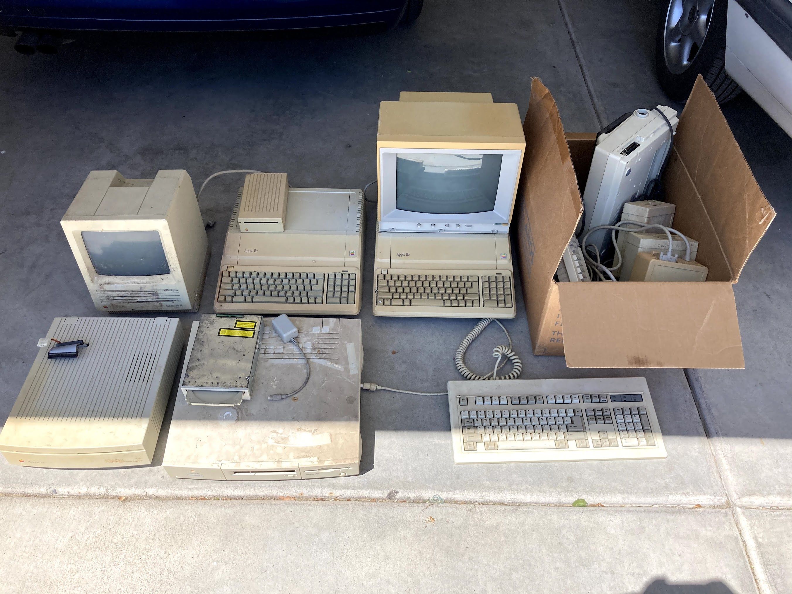
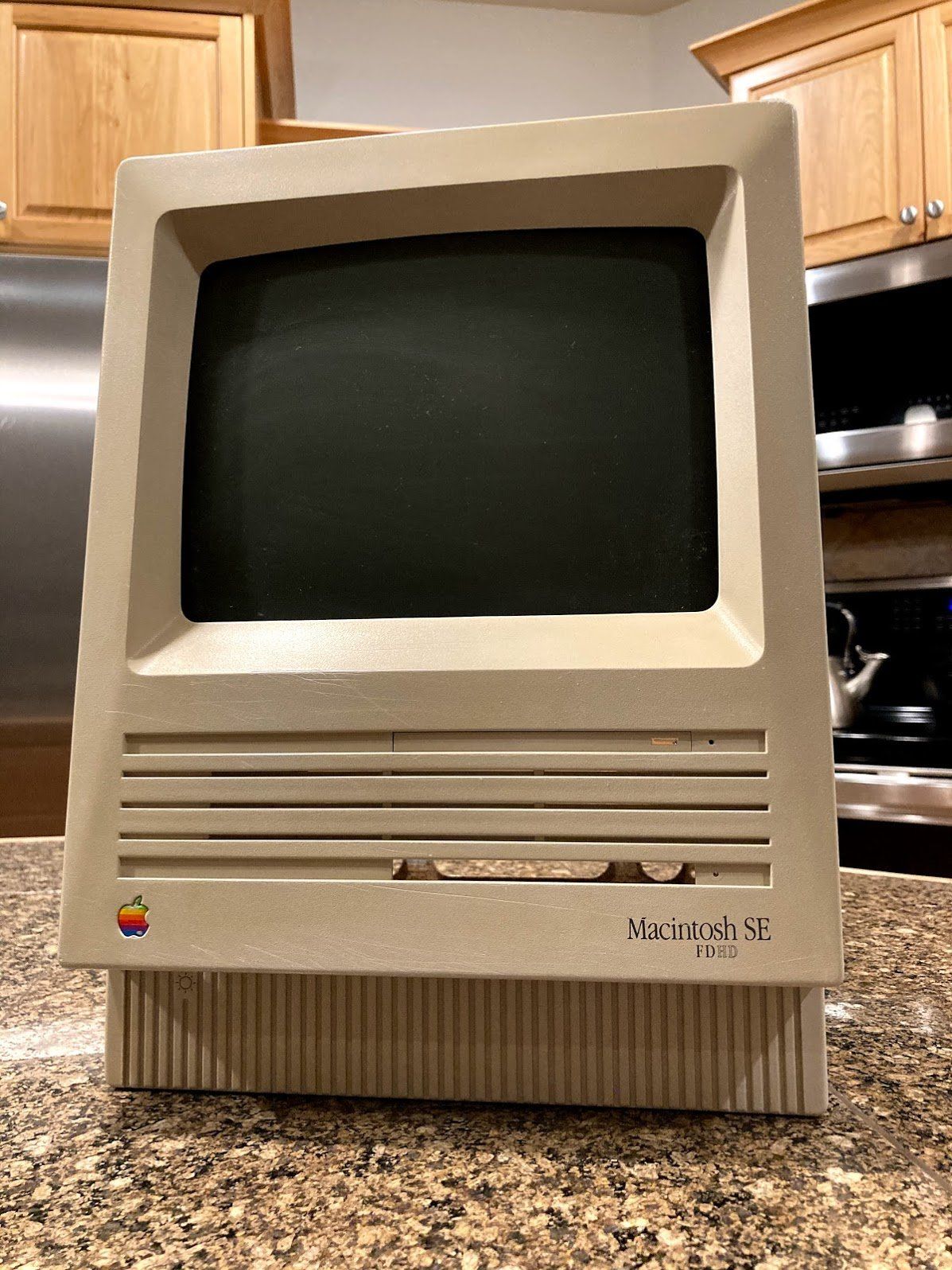
Last year, a friend of mine messaged me saying that he had “a bunch of old Apple stuff” for me. Apparently, it had all come out of his parent’s basement (a factor that will come into play later). In the pile was a little Macintosh SE FDHD.
The FDHD stands for “Floppy Drive, High Density” (or something like that), and can read 1.44 mb floppy disks. Not only does it have a high-capacity floppy drive - it also has a ROM that can take advantage of it, which makes it more special and usable than a typical Macintosh SE. Later versions of this were labeled “Macintosh SuperDrive”, which I feel was a nice branding improvement.
Teardown
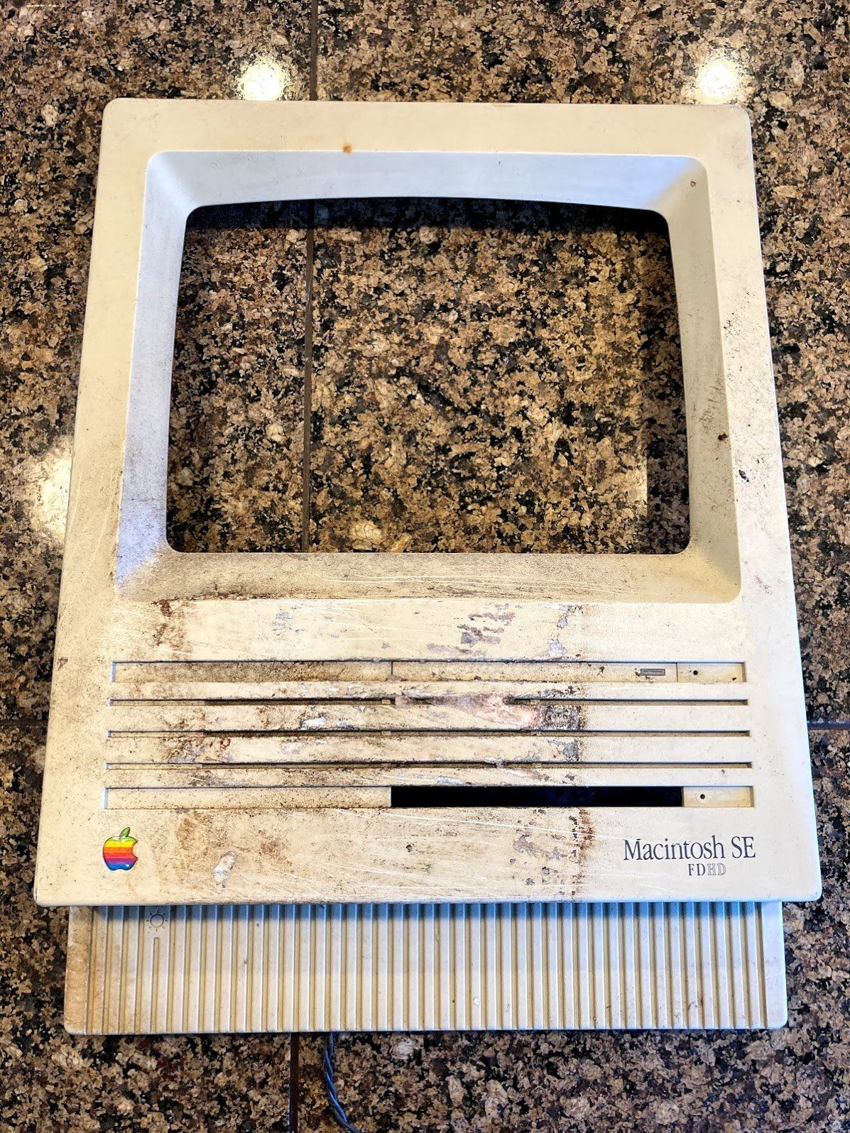
Here’s what we have to work with. It is extremely dirty, and the front is obviously very, very scratched. At this point, I couldn’t tell the condition of the CRT because of all of the dirt. This is by far the worst-looking compact Mac I’ve ever seen.
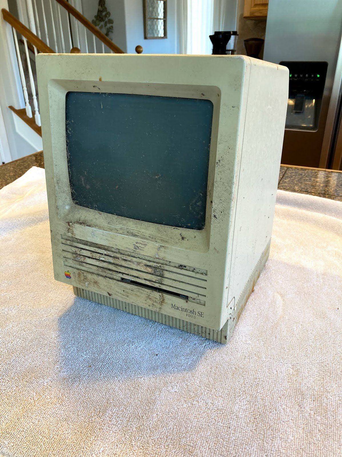
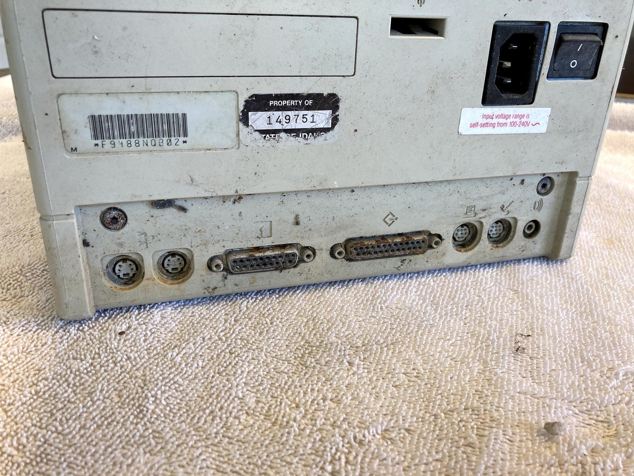
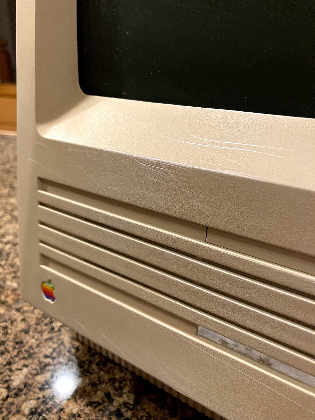
Notice the rust stains around the bottom. Not a good sign.

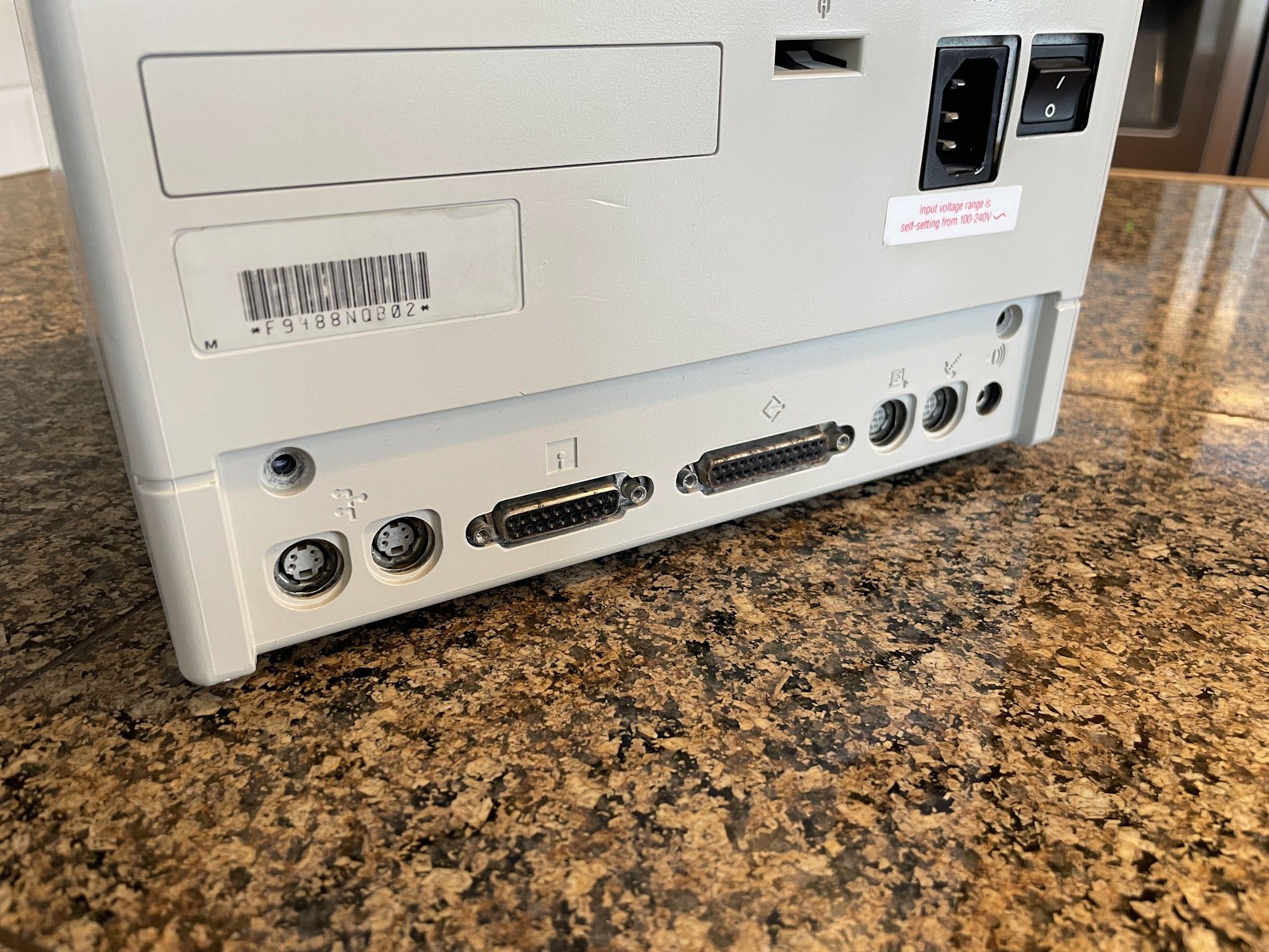
It gets worse. Check out the connectors on the back. At this point, it was becoming very clear to me that there was serious water damage. There’s the remains of a “Property of the State of Idaho” asset tag, which is interesting. I’ve seen 3 or 4 machines with this exact tag.
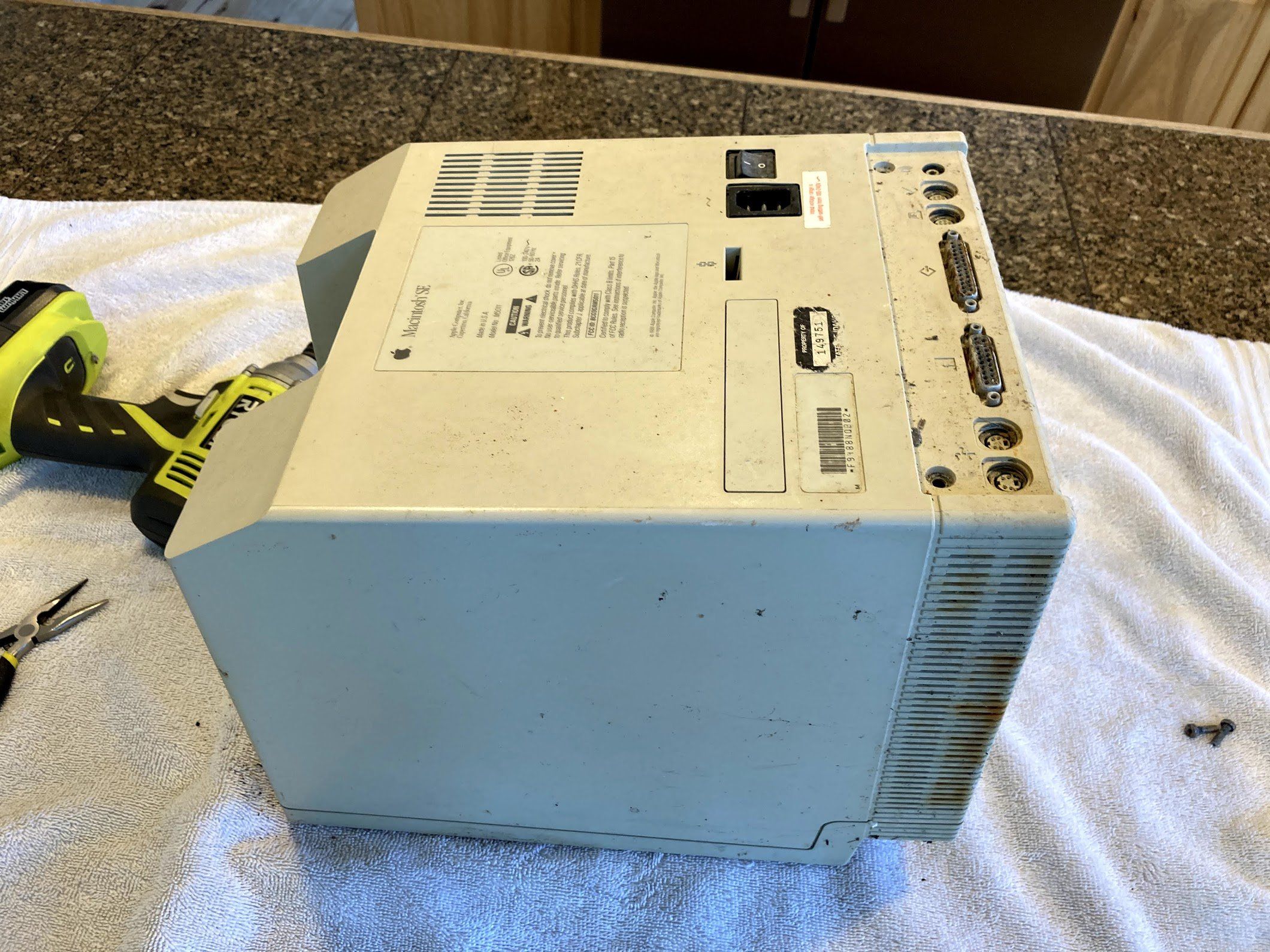
Expecting the worst, I grabbed my impact driver and broke the screws loose. I was pretty anxious to get it apart.
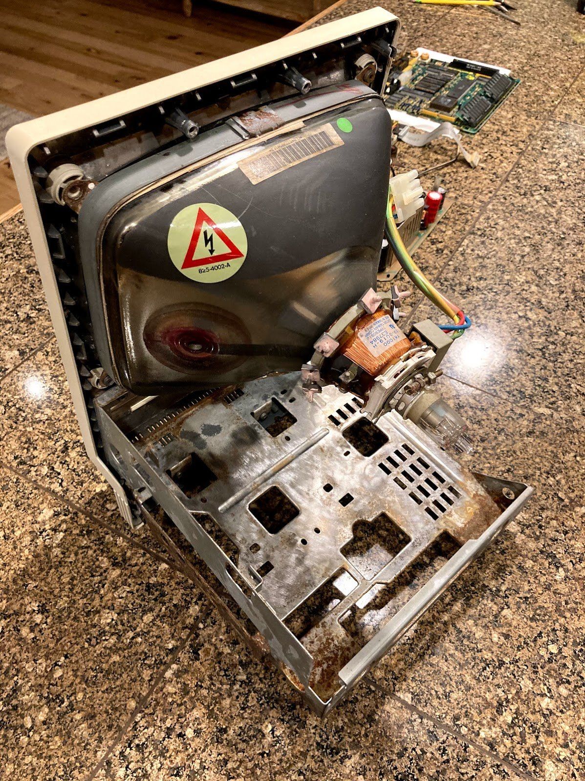
I wiggled the back bucket off, and this is what I was greeted with. Yikes. I seems that this machine sat in some water for awhile. I learned that the machine was in a 1940’s basement that flooded a couple of decades before the machine came to me.
At this point, I was thinking, “Well… maybe the CRT could be useful in another machine.” Or maybe, “I guess I can salvage the flyback.”
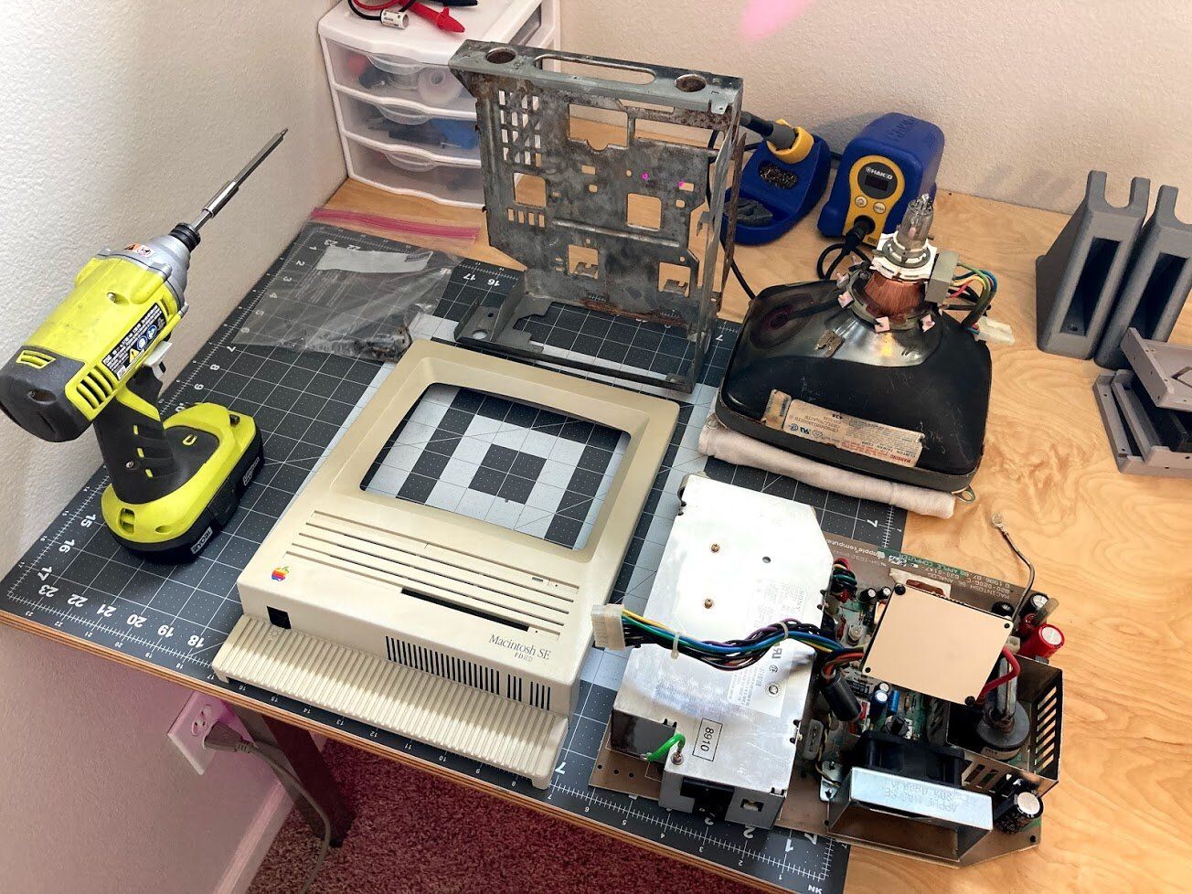
I decided to keep going, and tear it completely down to see what I had to work with. Just to be safe, I followed the CRT discharge procedure of clipping a wire to the chassis and a screwdriver, and sliding the screwdriver under the anode cap. I’m sure this machine hasn’t been powered on in ages, but better safe than sorry. I’ve done this on many compact black-and-white Macs, and I’ve never heard so much as a “click” from a small arc, but I always do it anyway.
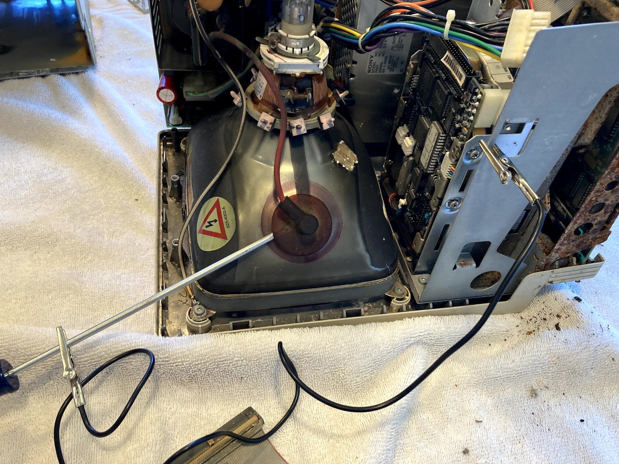
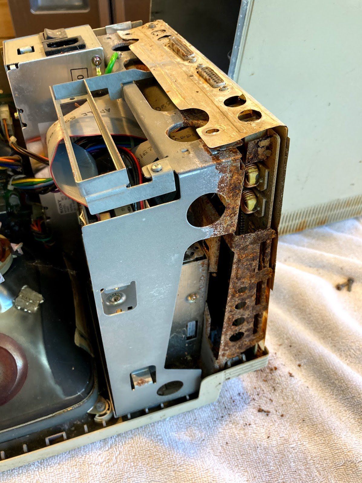
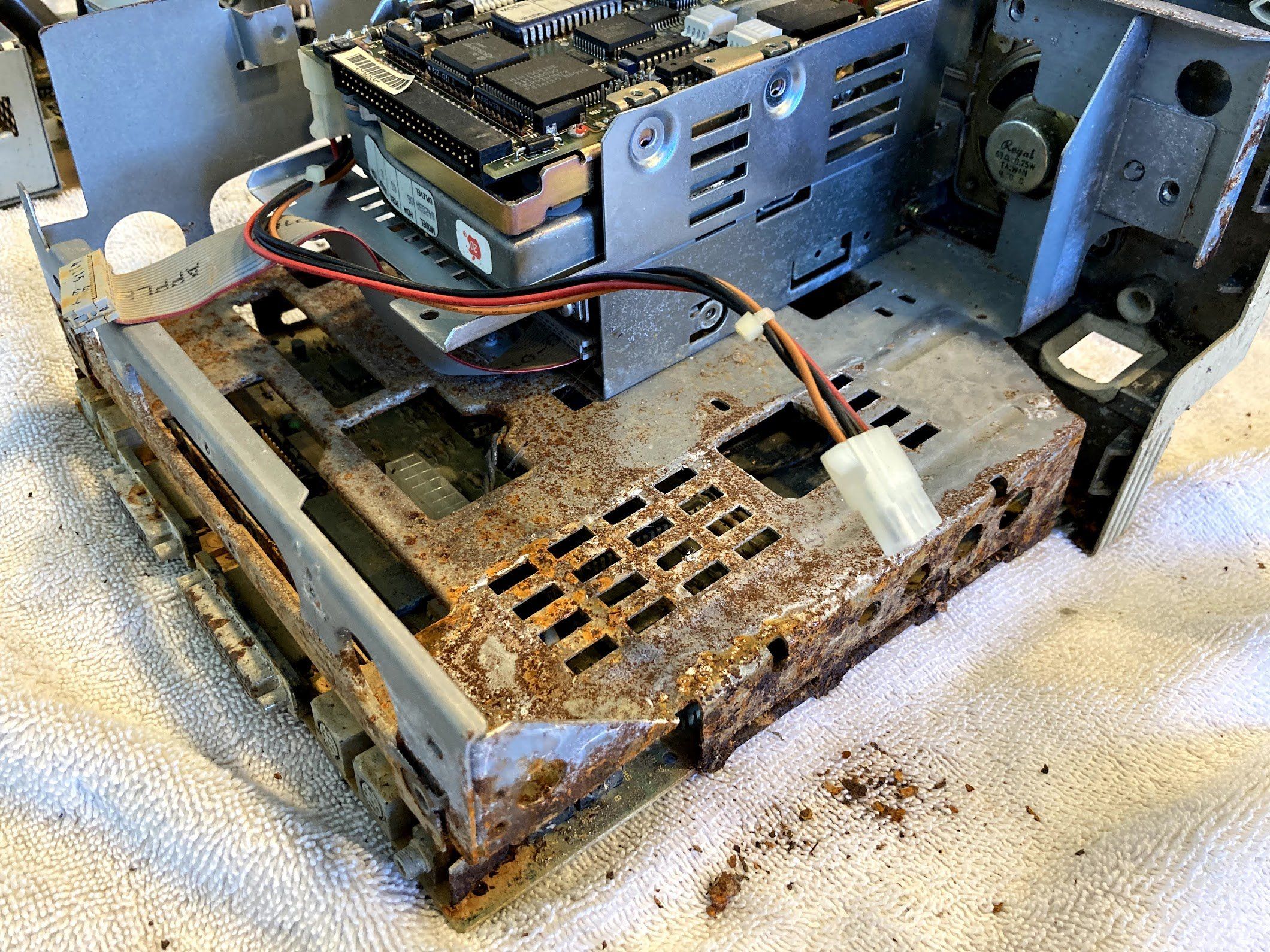
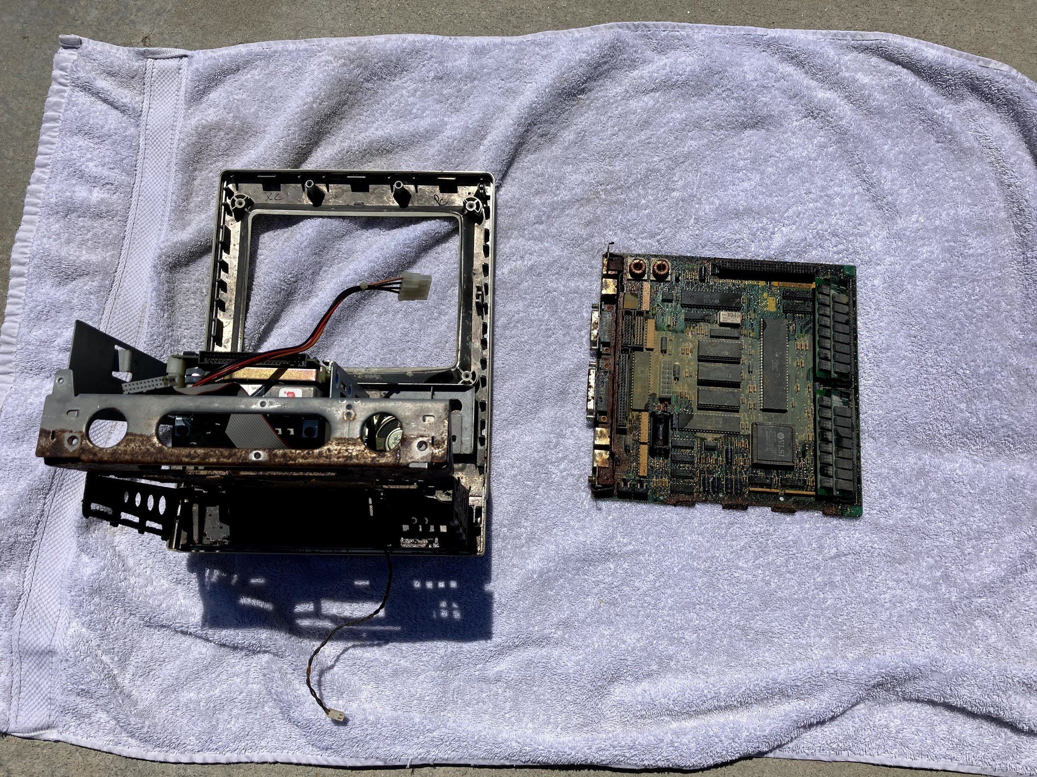
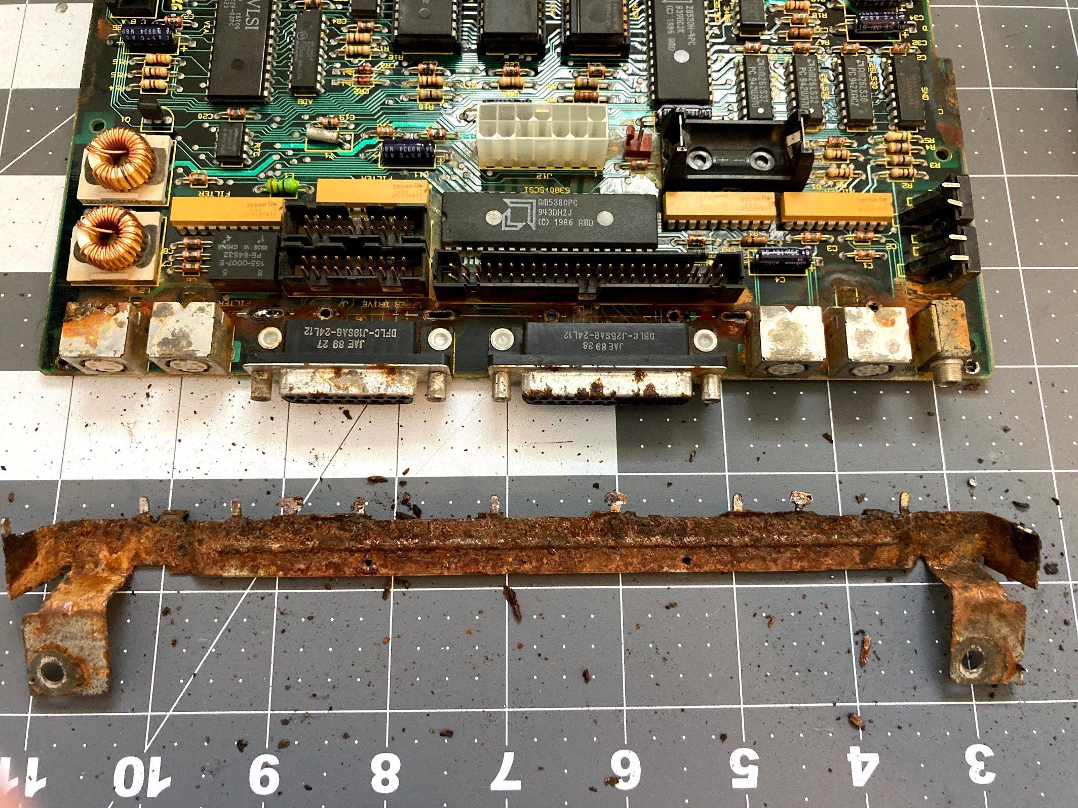
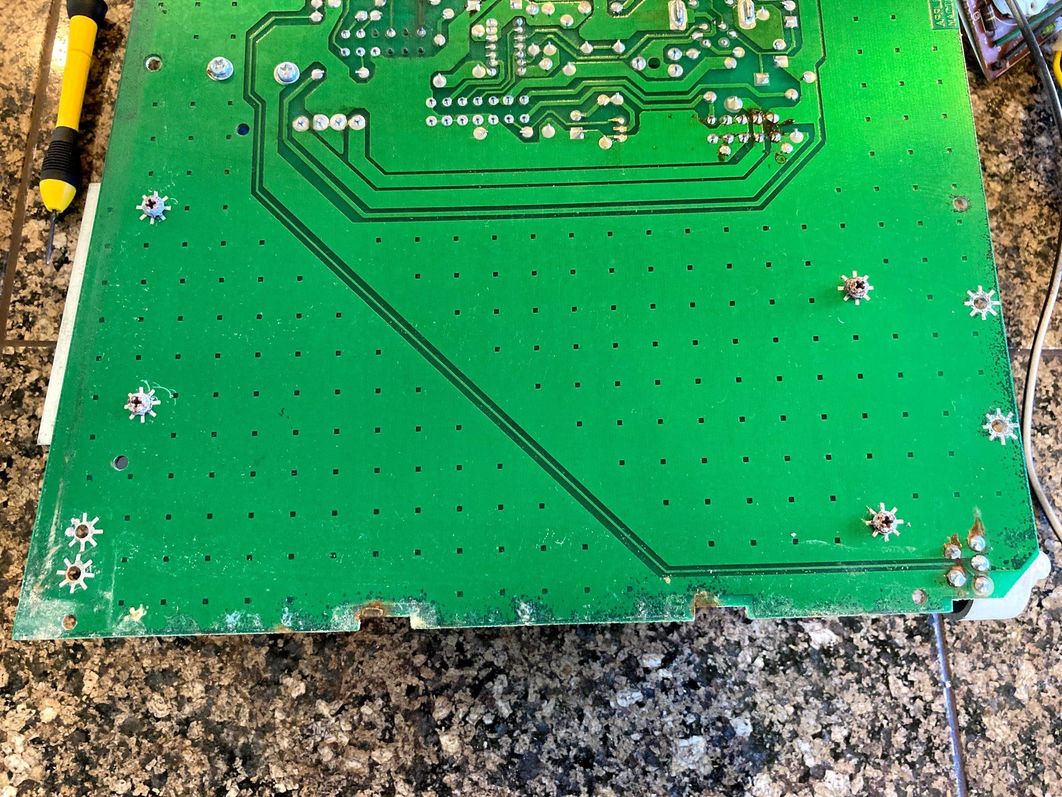
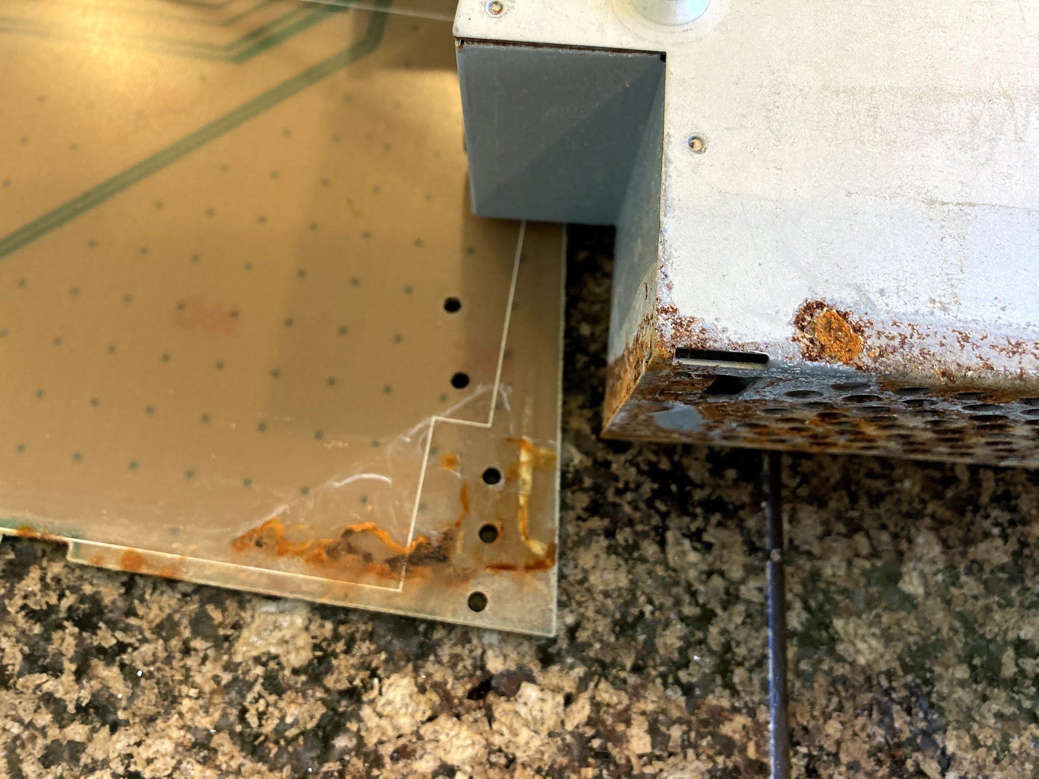
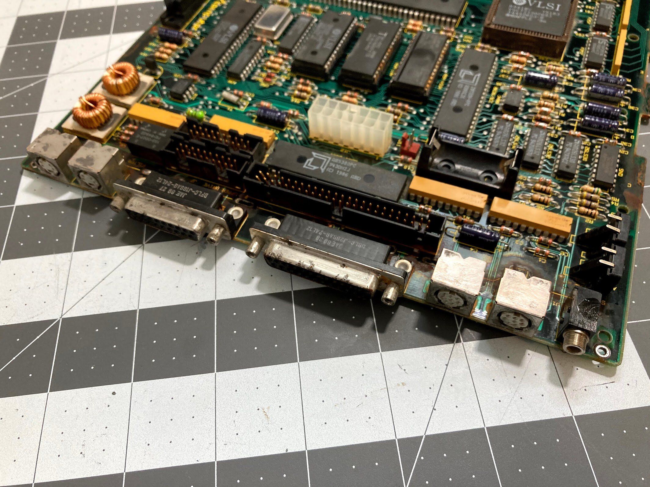
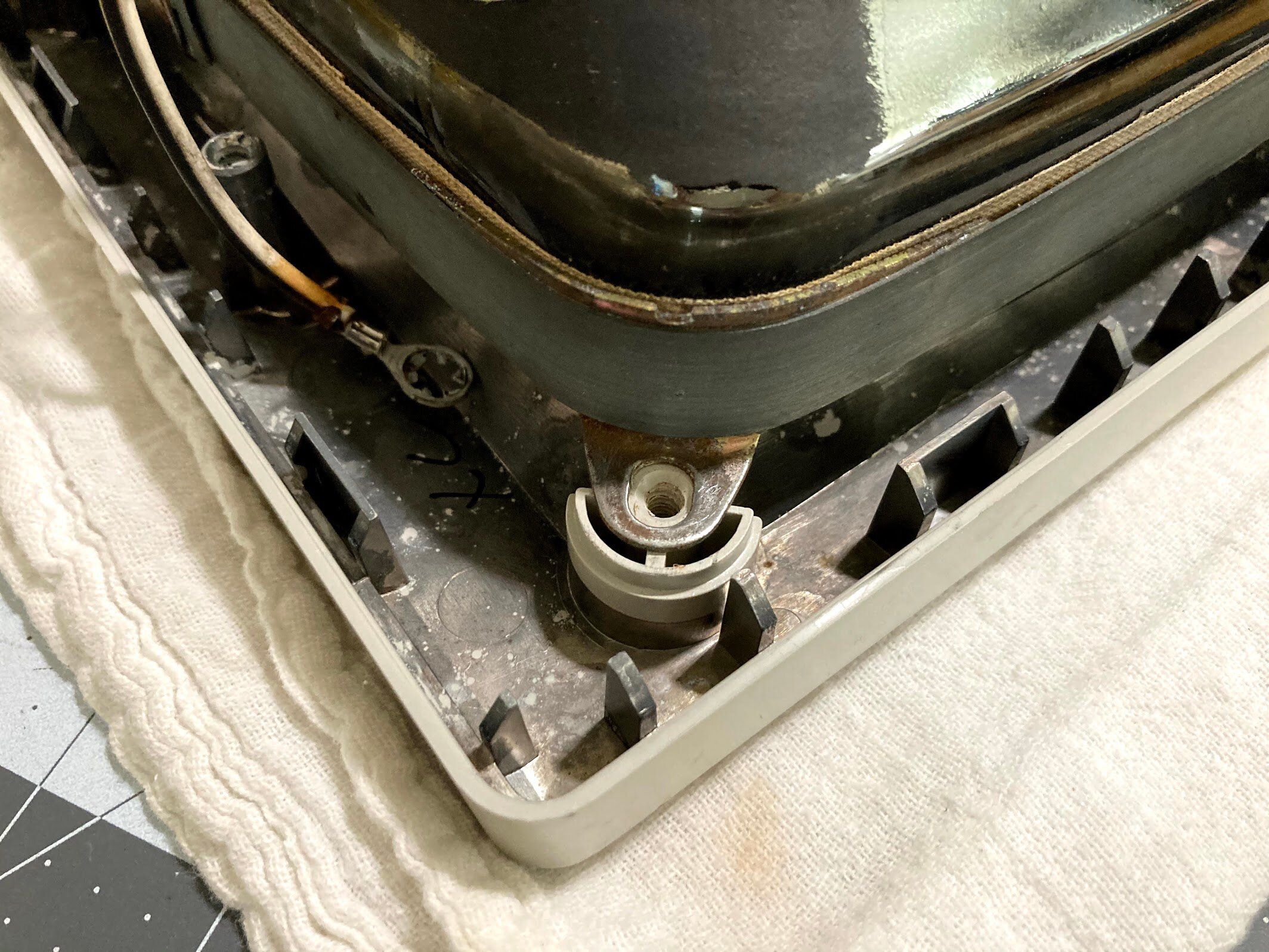
With the CRT discharge out of the way, I could starting tearing it down. But… where to start? The logic board was so rusted in that it wouldn’t budge. I decided to unplug the floppy and hard drives first, but those were a struggle. Next, I removed the analog board. Check out the literal “water line”. You can see exactly how far up the water came.
With the analog board removed, let’s show another photo, just to drive home how totally trashed this machine is. My impact driver was key to getting a lot of the rusted screws loose.
Logic Board Removal
Next, I took the machine out to the garage to try to figure out how to get the logic board out. I don’t have any photos of this, but I managed to get a screwdriver down to the battery and pop it out of the holder. Amazingly, it hadn’t blown up. If you’re interested in vintage Apple machines, know that batteries are the number 1 killers of these machine. If you haven’t removed the battery from your vintage Mac, stop reading and go do it right now.
I soaked the logic board rails in some WD-40 to try to loosen things up, and let it sit for a few hours.

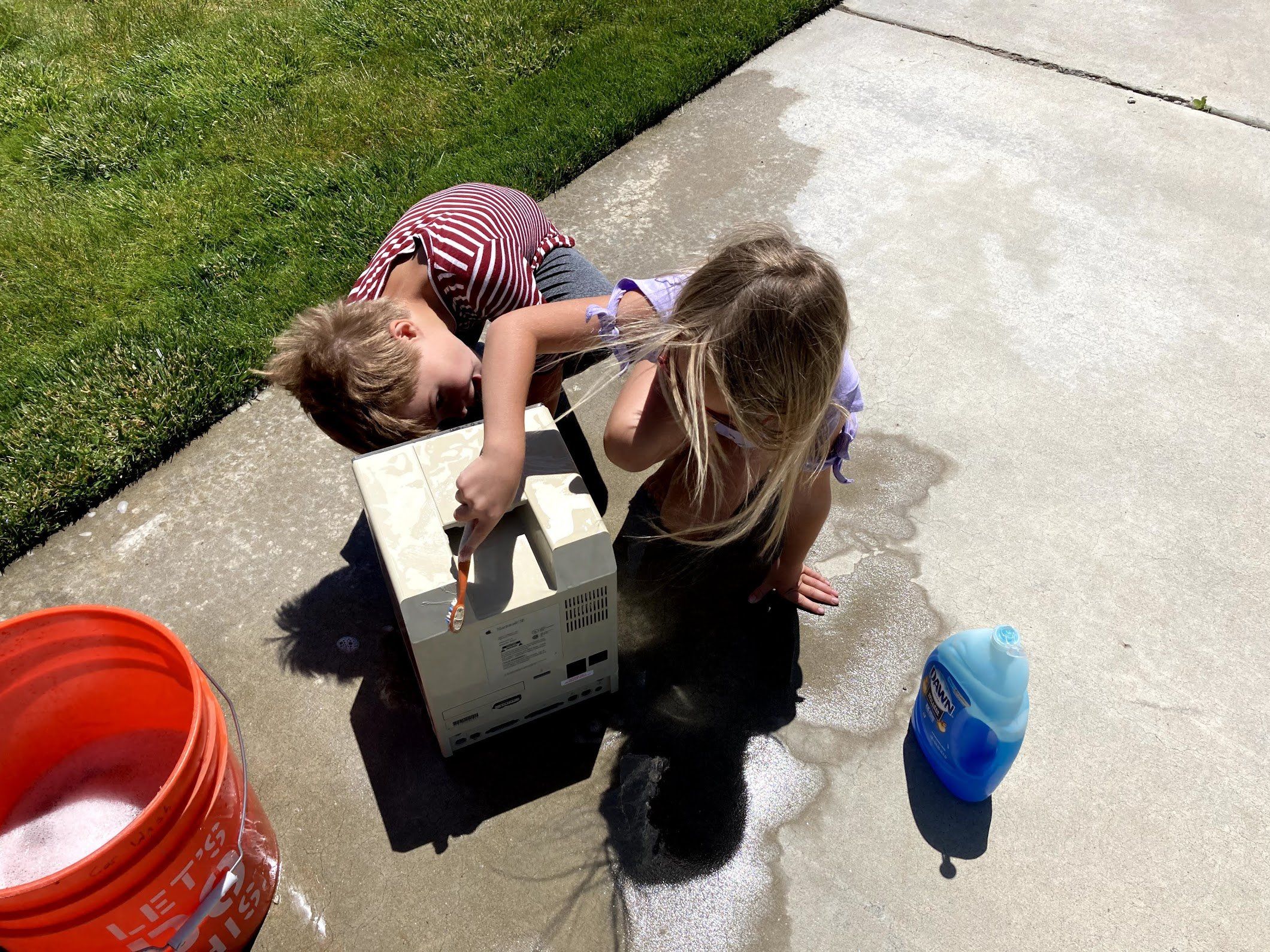
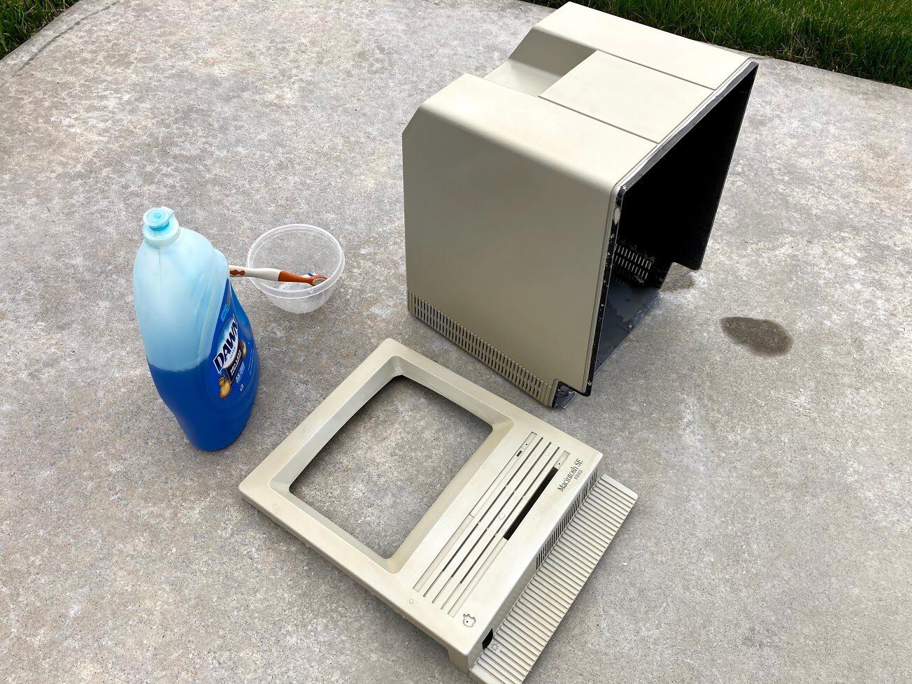
While that sat, my daughters helped me clean up the back bucket a bit. We used Dawn dish soap and toothbrushes, as usual.
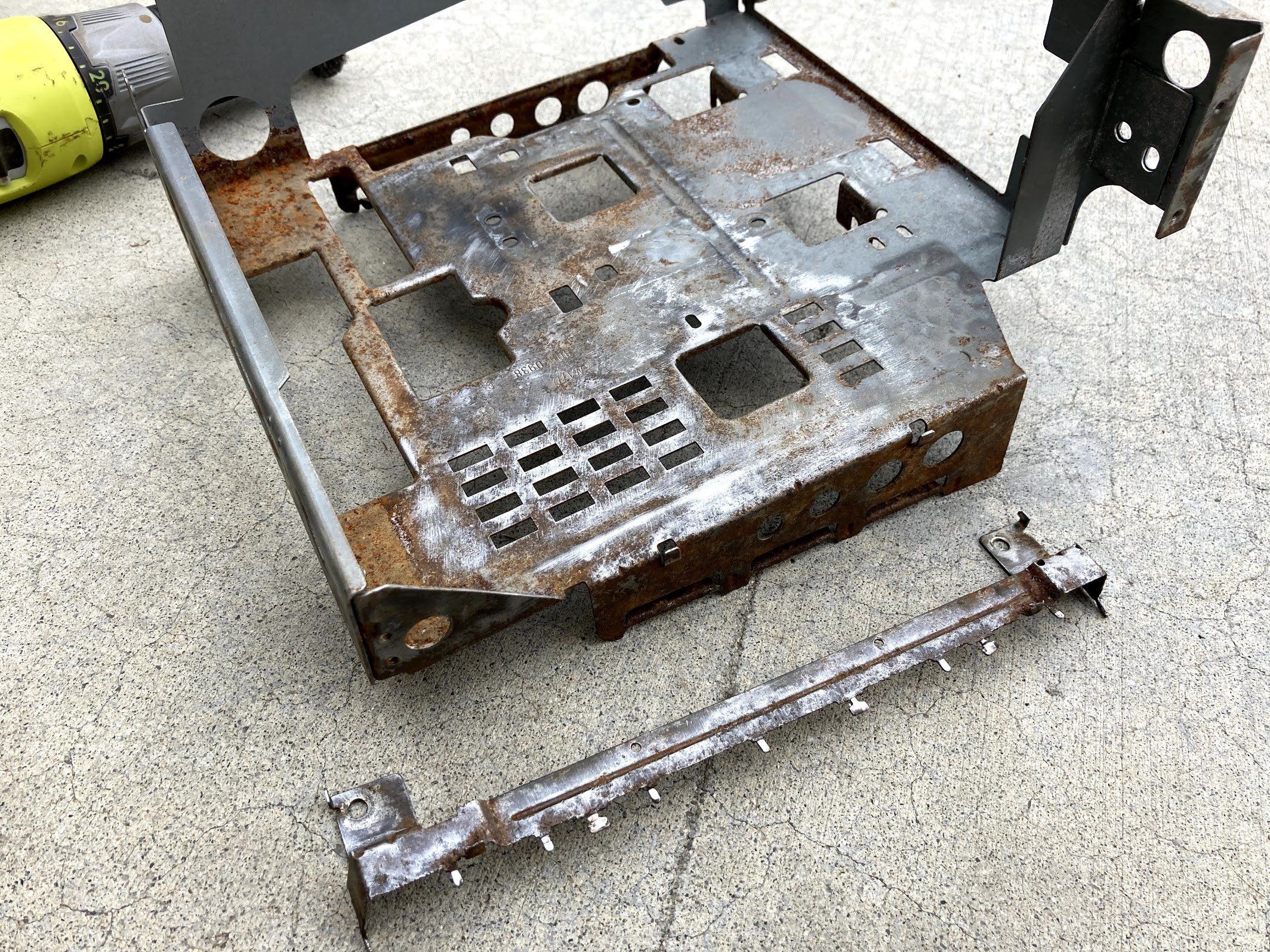
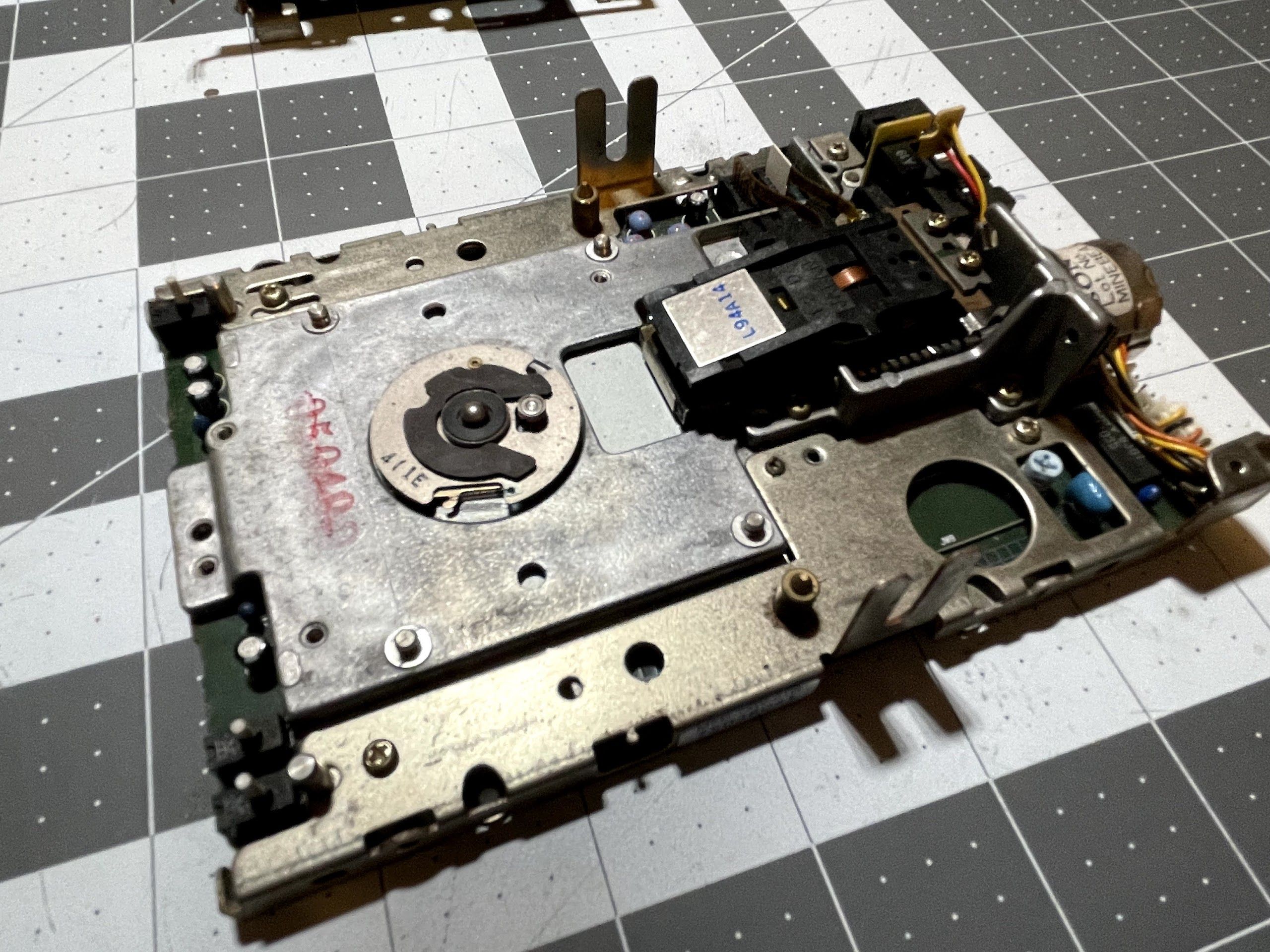
With a bit of persuasion, I was able to get the logic board out. I ended up jamming a screwdriver in between the logic board and blending the rails out slightly to remove the board. They didn’t permanently deform, but they did move just enough to sneak out the board. Sliding the board out was a complete impossibility.
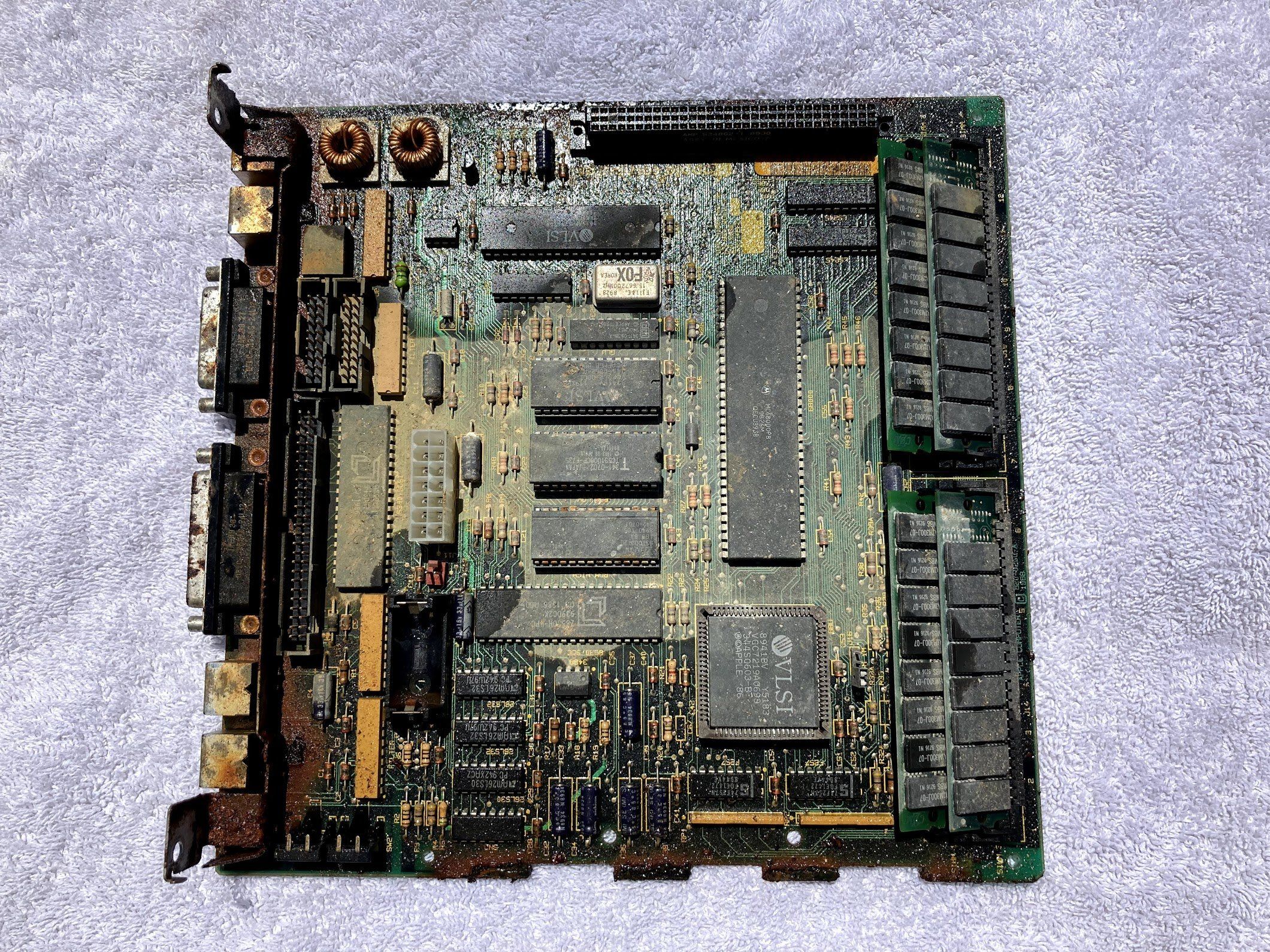
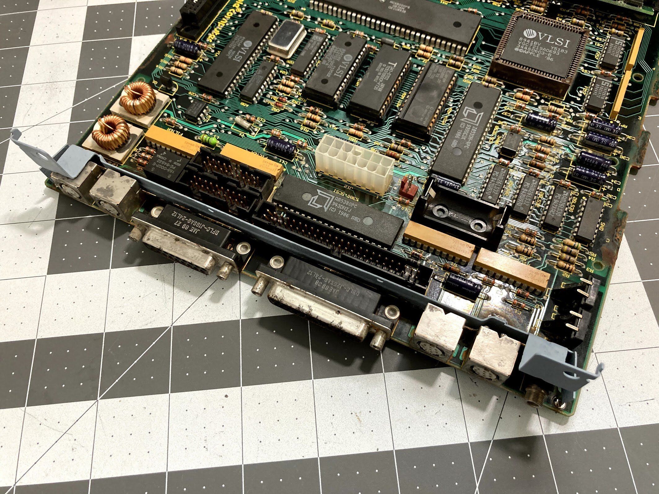
Here’s the logic board up close. I think this is the point where any sane person would stop. But me? No. I decided to keep going.
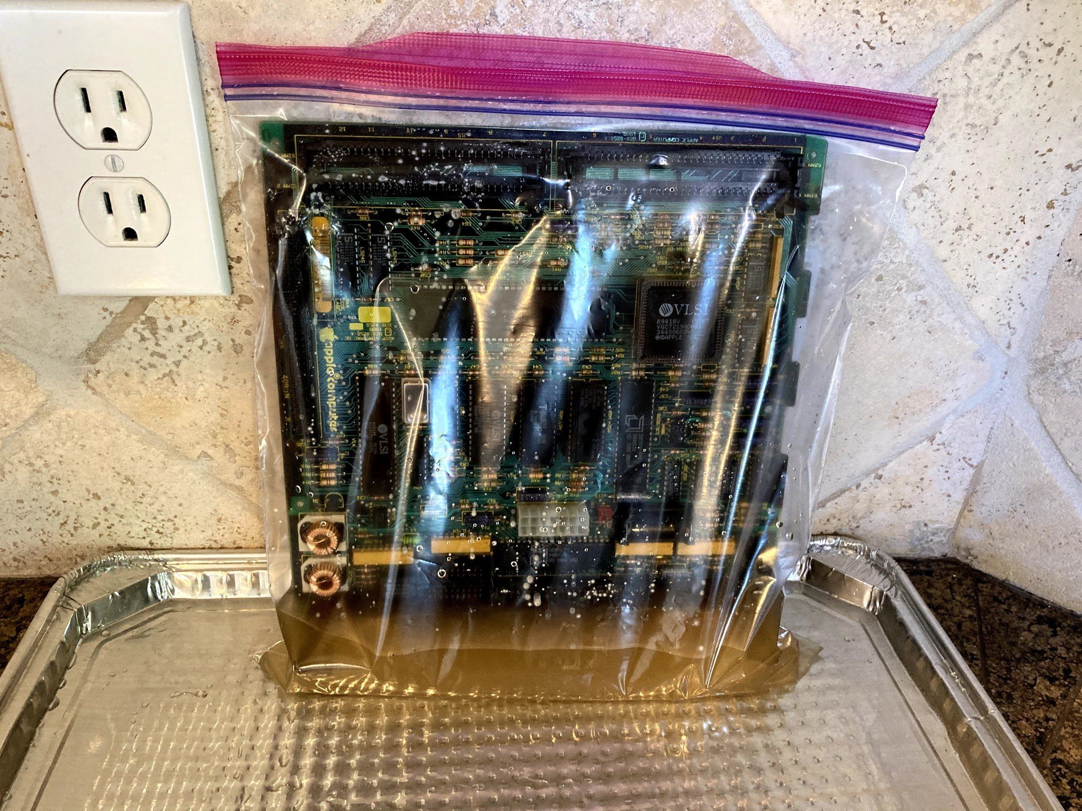
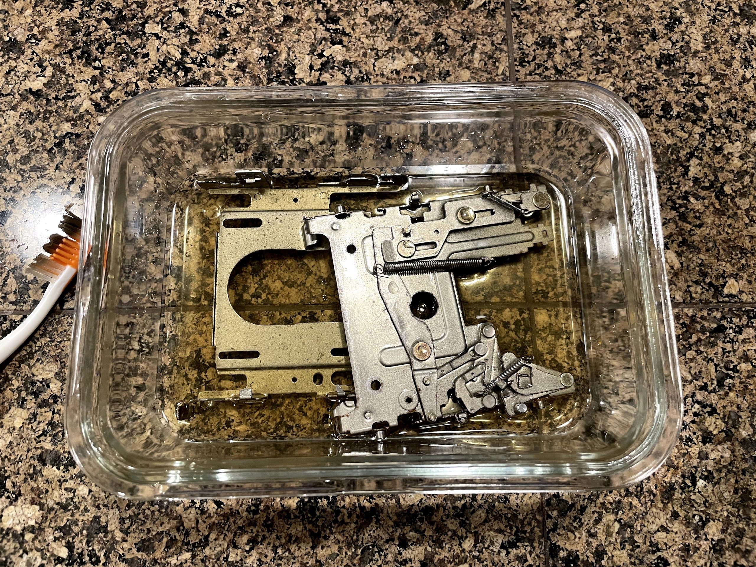
I hit the logic board with a garden hose, and then stuck it into a tray of vinegar to try and neutralize some of the rust.
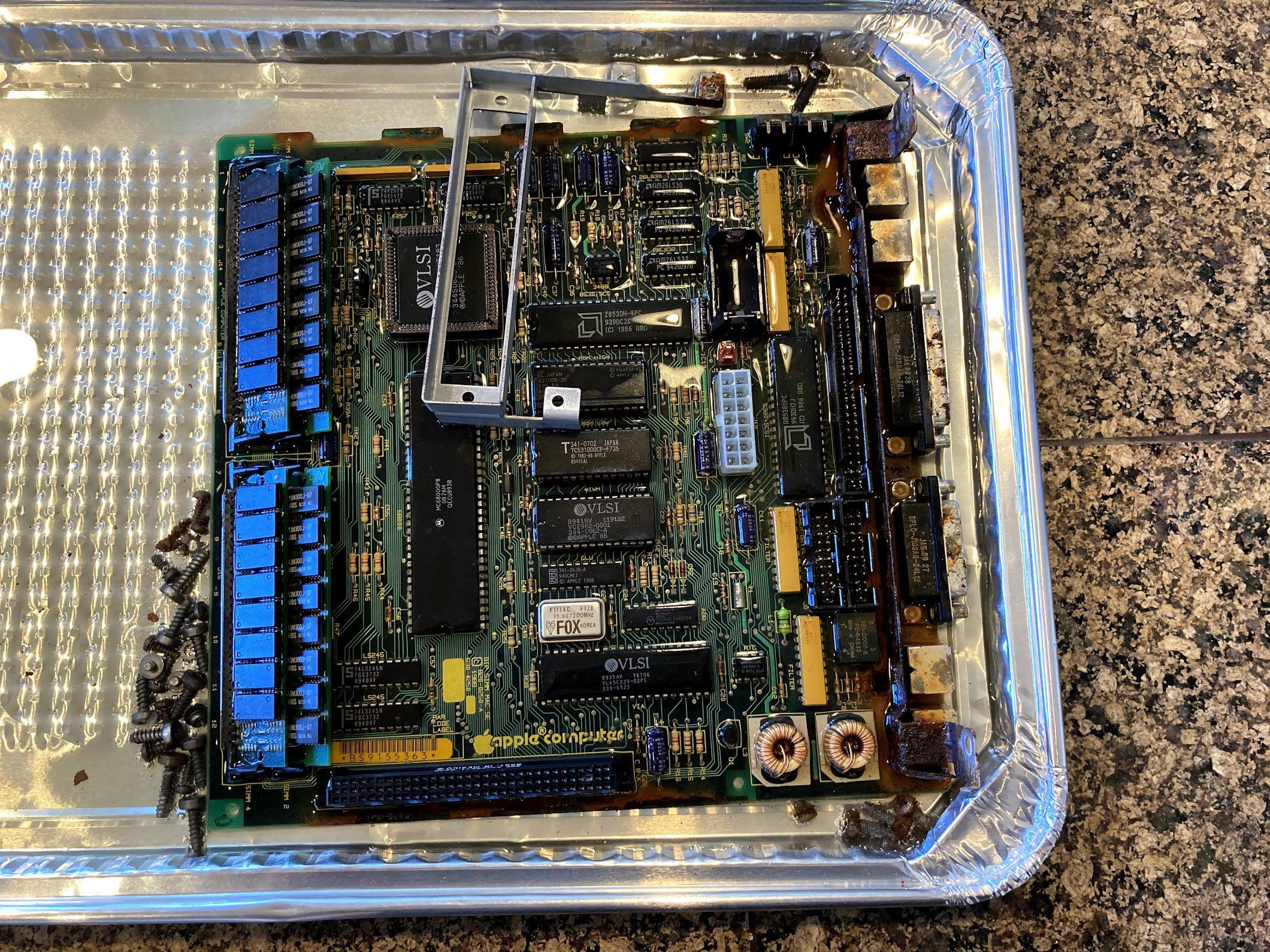
I stuck the chassis screws in as well. It’s fun to watch the vinegar work on them!
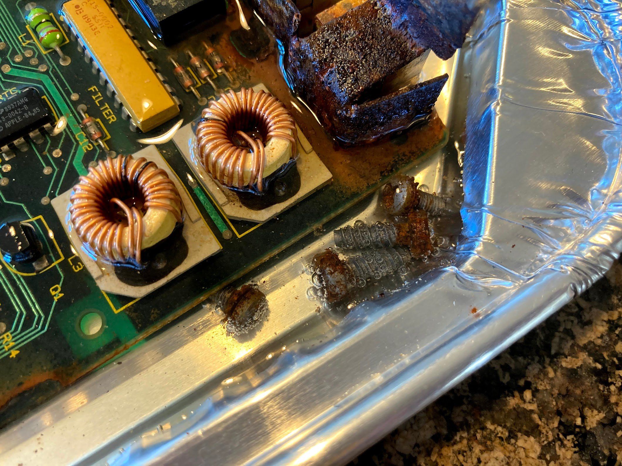
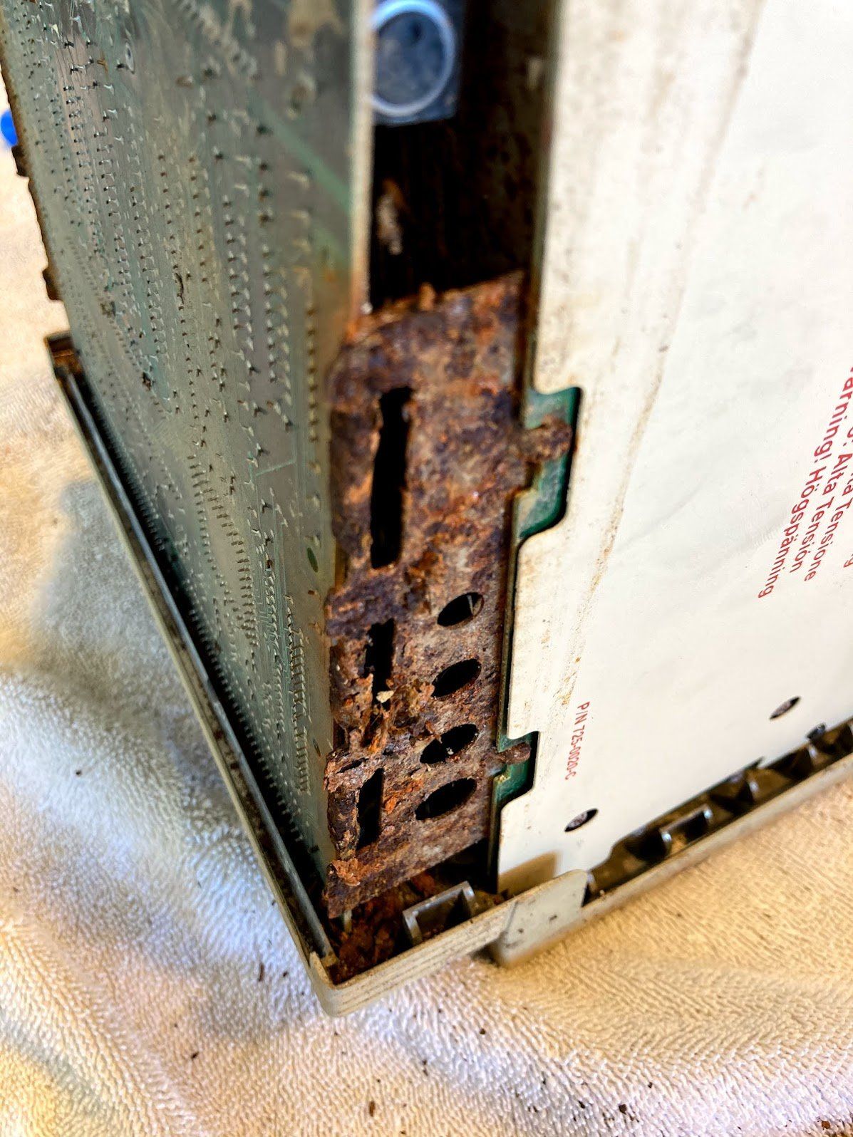
I found the rust around the I/O ports to be particularly concerning, but decided to let the vinegar work.
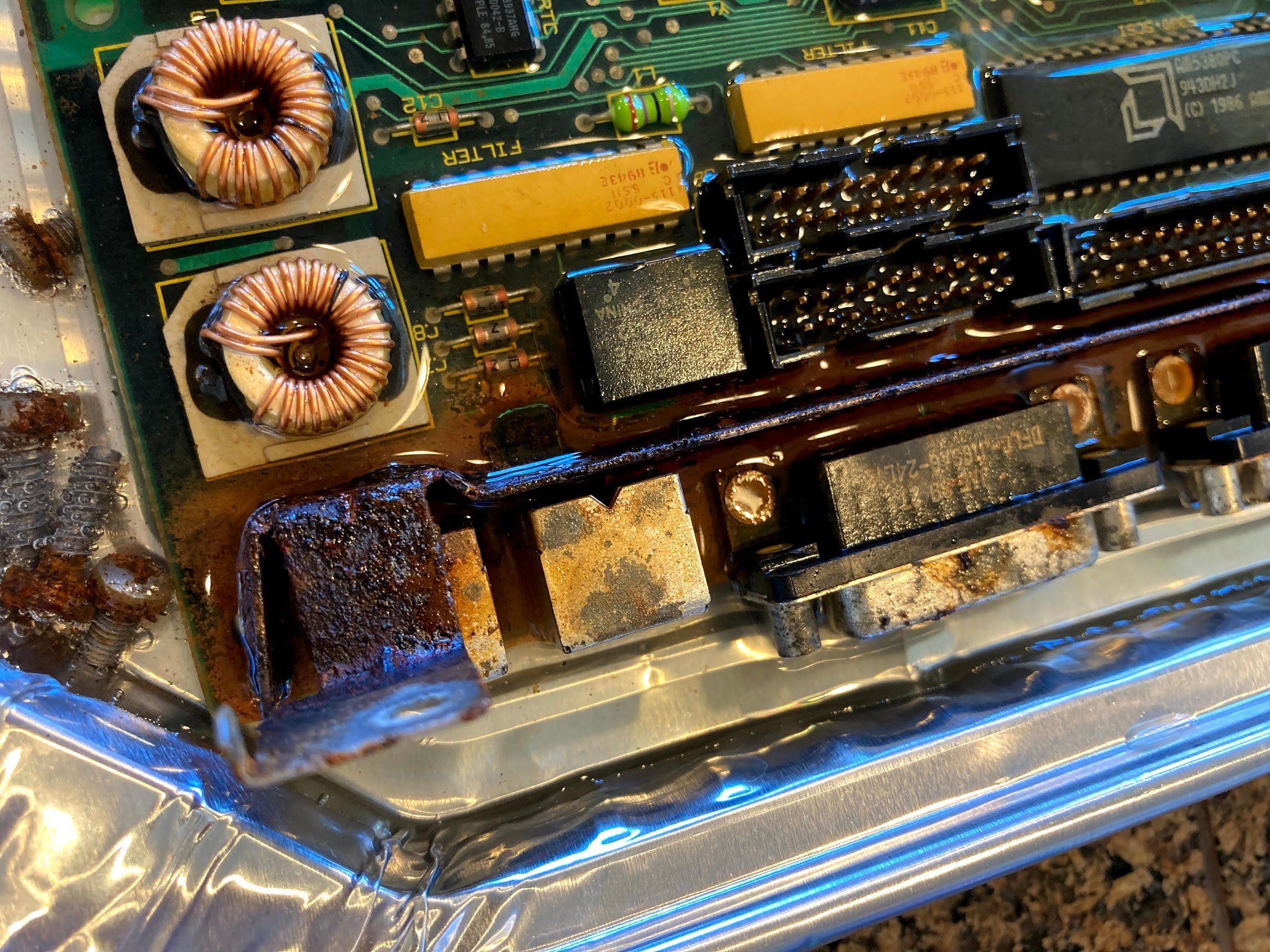
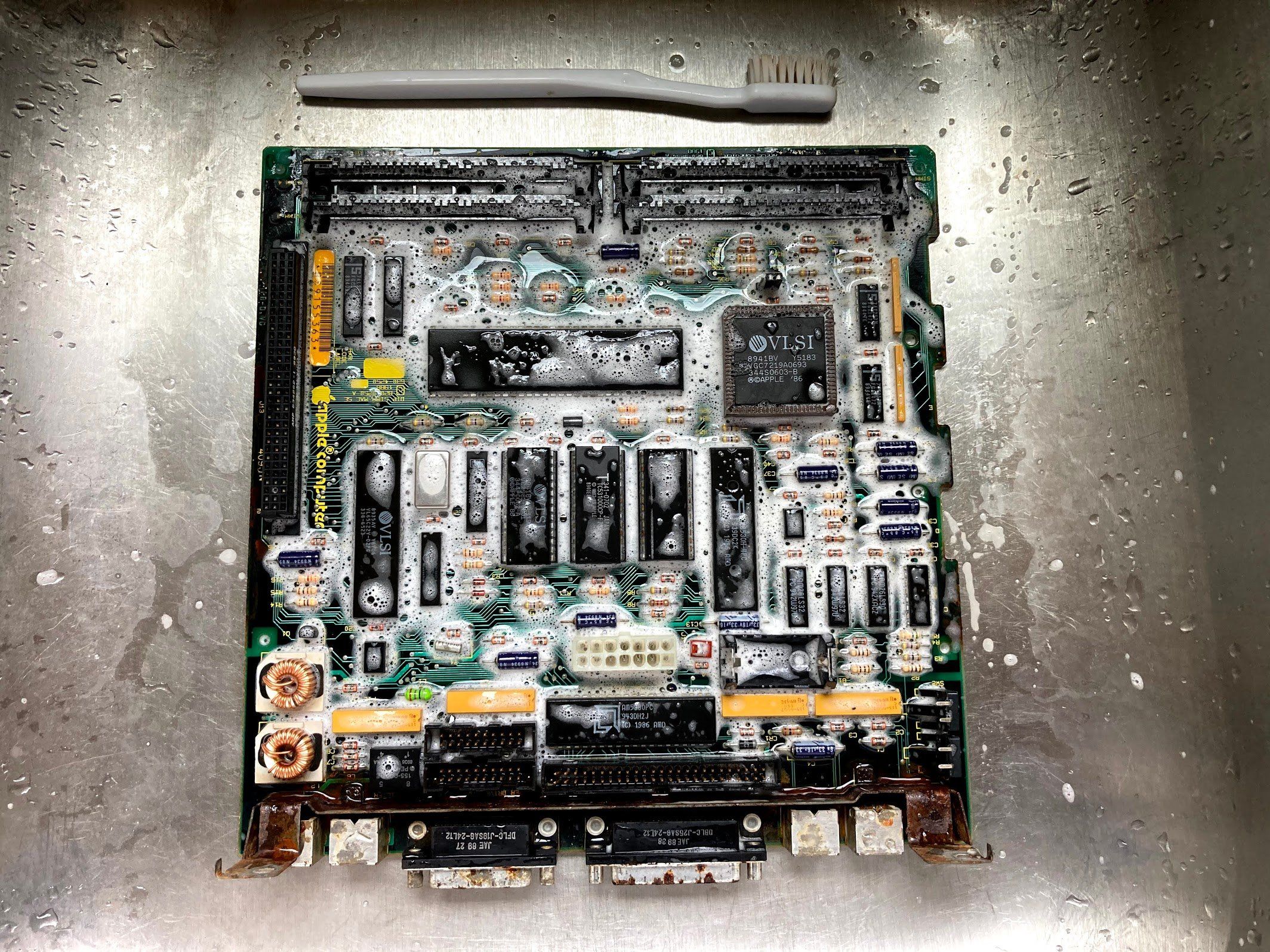
I scrubbed the board with a toothbrush after a couple of hours, and was surprised at how much it cleaned up. But there was still a ton of rust around the I/O ports, so my wife helped me find a creative solution to submerge the I/O ports with the limited amount of vinegar that we had on hand at the time (with the shortage due to COVID-19).
Logic Board Shield Removal
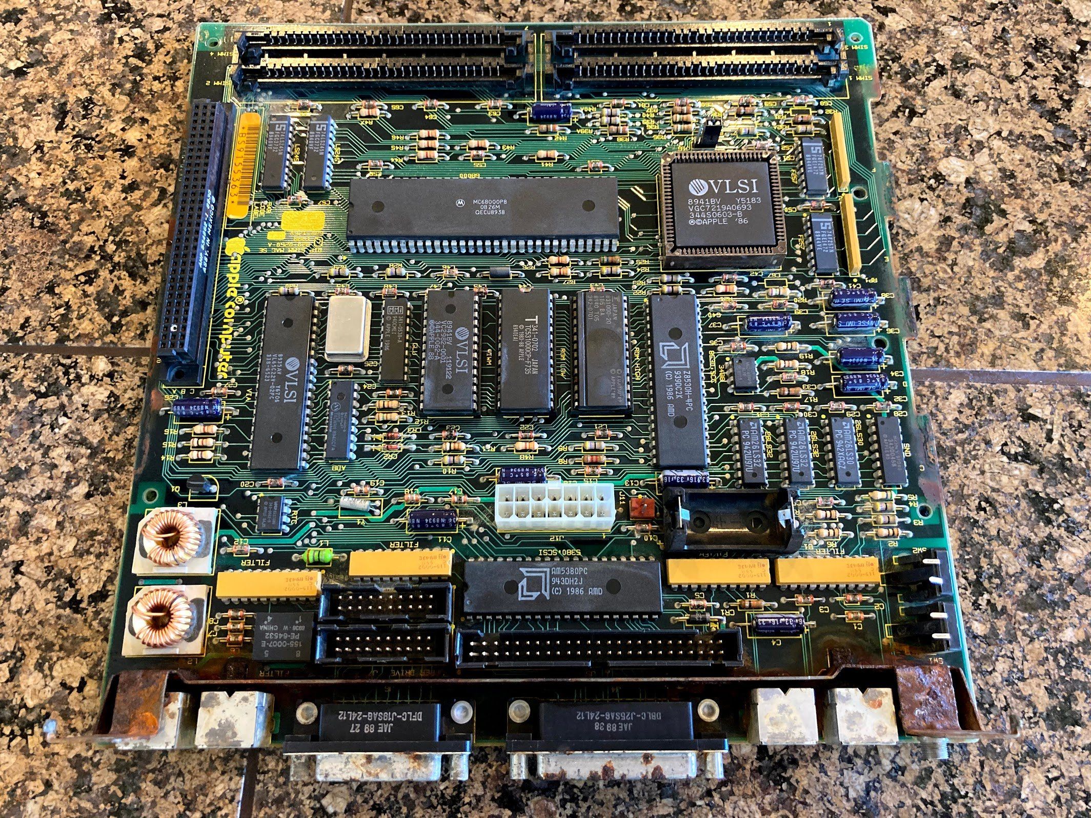
After sitting in the vinegar all Sunday afternoon, I pulled the logic board out and took it back to the sink for a soap and water scrub. It’s funny, a few years ago I would have never dreamed of putting a circuit board in the kitchen sink, much less hitting them with the garden hose like I did this with this one. Now… I scrub them down with soap and water all of the time.
As soon as I was done scrubbing, I took it out to the garage and hit it with the air compressor. Not bad… I think there’s signs of life here, but the shield near the ports on the back is proving to be especially rusty and offensive. I decided to try removing it.
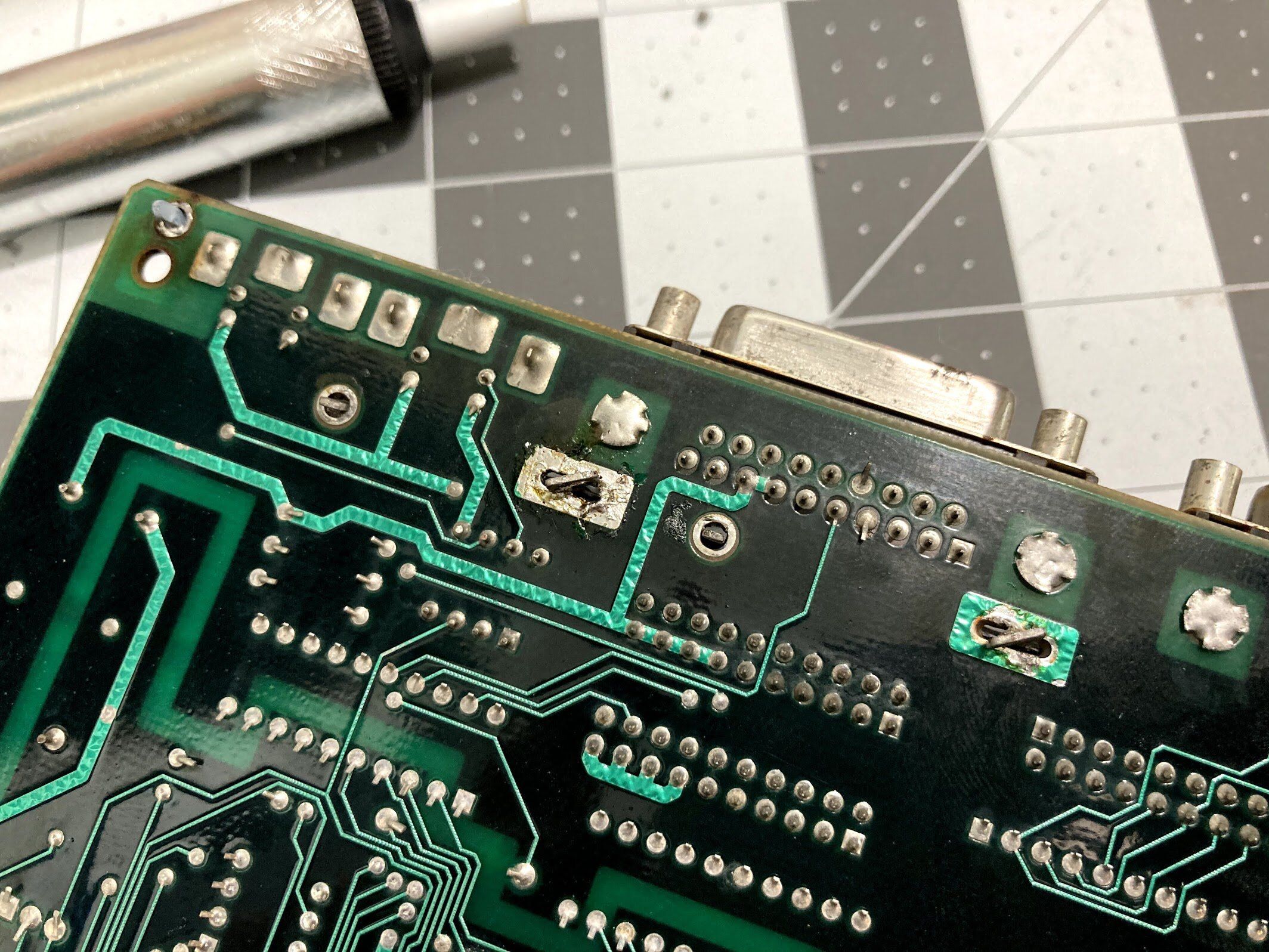
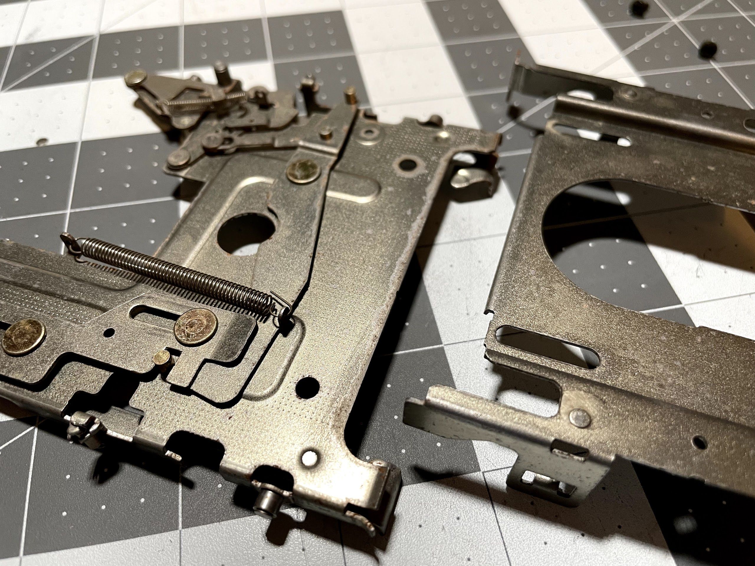
Looking at the underside of the board, I located the solder joints that hold the shield in place. I set my soldering iron almost as hot as it will go: 990°F. Next, I coated one of the joints in flux paste.
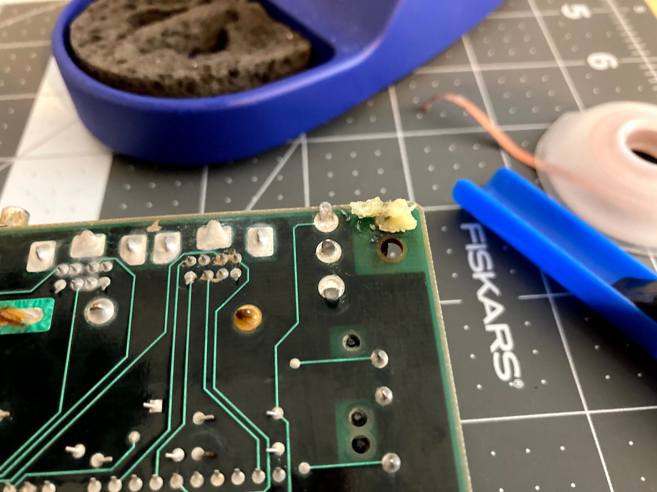
I heated up the joint with the iron. At a certain temperature, the flux, solder, corrosion, and rust started to pop, bubble and fizz! When the solder turned molten, I sucked it all away with the solder sucker. It worked great!
It was the same story on the rest of the joints. I think the secret is lots of heat, and lots of flux.
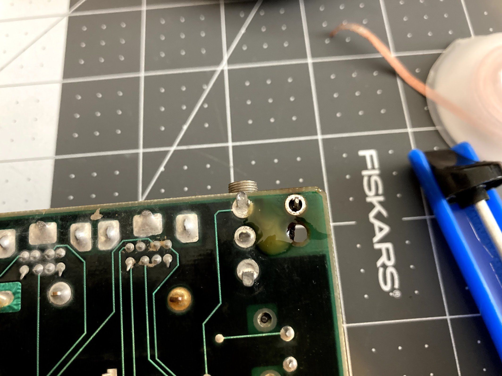
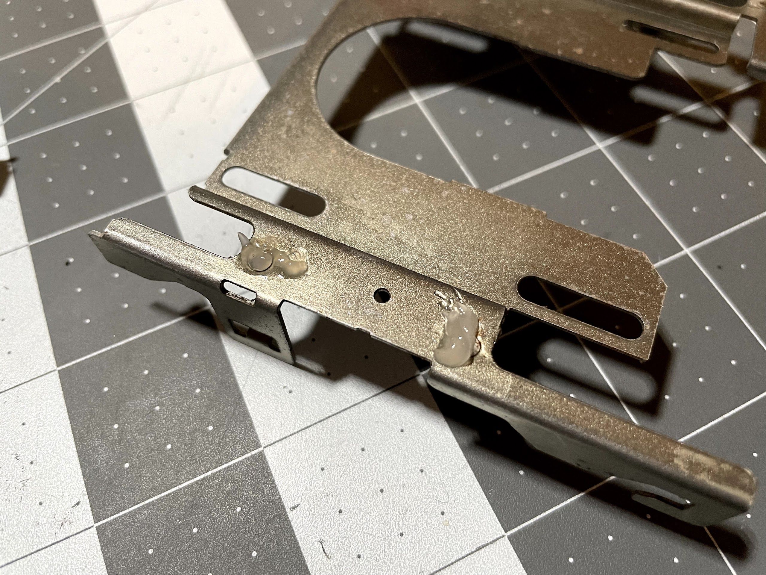
There are some tabs that are twisted about 22° before soldering, so I straightened them back out so I could pull the board through.
With all of the solder removed, and the tabs straightened, it was time to remove the shield. I had my wife heat a couple of joints for me while I worked the shield loose. I knew that teaching her to solder would come in handy!
Cleaning
Next, I tackled getting the whole machine cleaned up, starting with the chassis.
Chassis
I took a small wire wheel on a cordless drill to both the shield and chassis. While this was a big improvement, but there were a lot of small corners that I couldn’t get into.
I would have liked to submerge it in vinegar for a few hours, but at the time, we were super low on vinegar. So, I decided to try something different: hot sauce, which is full of vinegar! I happened to have a bottle of “Mule Sauce” from Sticker Mule. Fortunately for the project, the hot sauce is just as bad as Sticker Mule’s politics, so it was a perfect candidate for this project (this is a Tabasco and Sriracha household).
Anyway, onto the chassis it goes!
My 7-year-old daughter said, “Dad, don’t you feel a little weird painting hot sauce onto your Macintosh?”
“Yes. Yes I do.”

I wrapped it in plastic and put it in the garage overnight.
So, did it help? Maybe a bit. I washed it all off in the sink and left it to dry, which was a mistake. When I came back, it had all surface rusted, so I didn’t get a great comparison. I hit it with the wire wheel on the drill one last time for now.
Enclosure
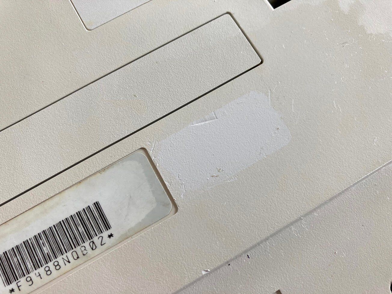
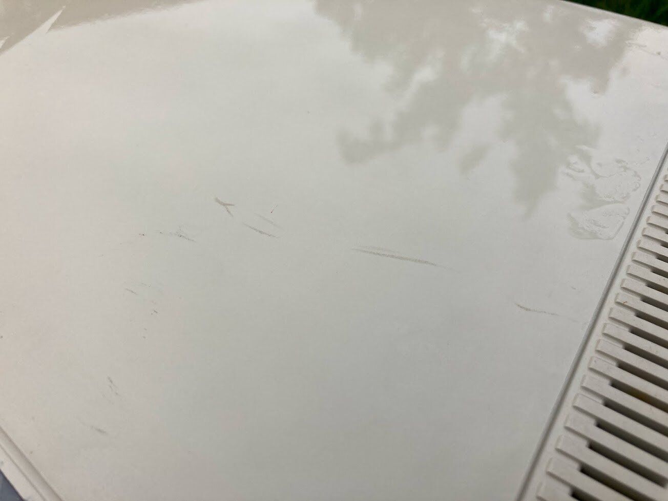
Okay, now that the chassis isn’t going to give us Tetanus just by looking at it, let’s talk about what I did with the front shell! Sadly I didn’t get any photos of this part, but I took it outside with my daughters, some toothbrushes, and Dawn dishwasher detergent, and we scrubbed the front like crazy. For the stubborn stuff (and there was a lot of stubborn stuff), I brought it inside and used wet paper towels and baking soda. This acts as a mild abrasive and removes stubborn scuffs and marks. It does also remove a bit of texture, but the scratches were so deep on this Mac that I was okay with that, especially on the chin. Where possible, I like to smooth out scuffs and scratches, even if that means losing some of the plastic texture.
To remind you, here’s before:
And here’s after, with the chassis and CRT re-attached.
The scratches on the front are pretty unfortunate, but after retrobrite, these will hide a bit more. You know, assuming that I need to retrobrite this machine for some reason. Because it’ll never run again.
Or will it?
Normally, I tend to tear the Mac down and do retrobrite before doing any kind of reassembly and testing, but for this one, I decided to start move towards testing sooner rather than later.
Also, my livingroom looked like this:
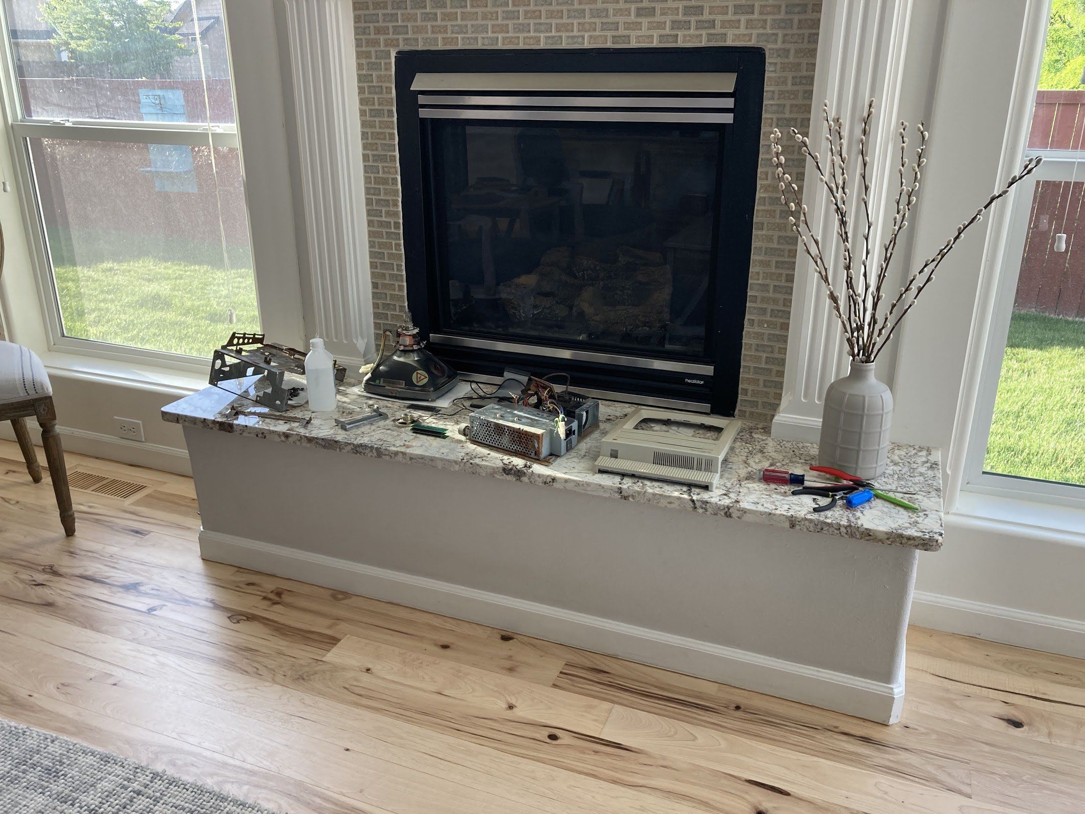
In an effort to make my livingroom look a lot less like that, I moved towards reassembling the machine.
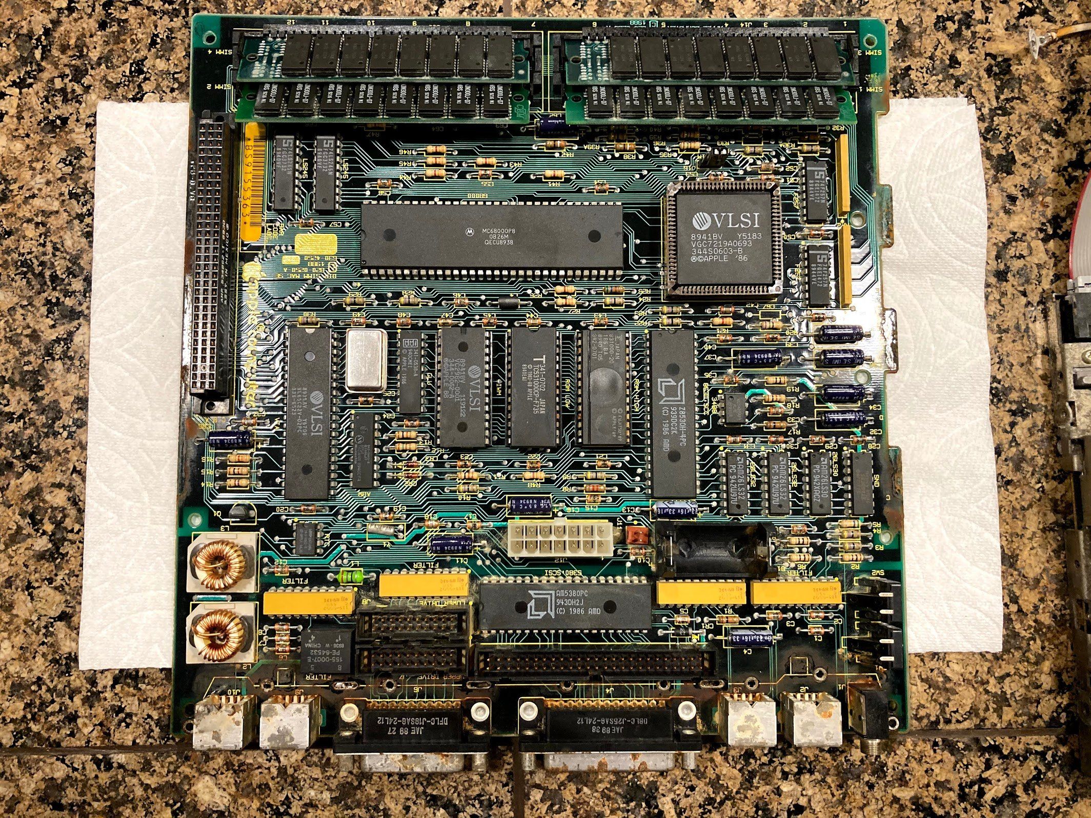
…and in the spirit of reassembly, I decided to tackle the RAM. I hit the contacts with an eraser. You can clearly see that the stick on the right has been cleaned in this photo.
Here’s the board again, mostly cleaned up with the RAM reinstalled.
Analog Board
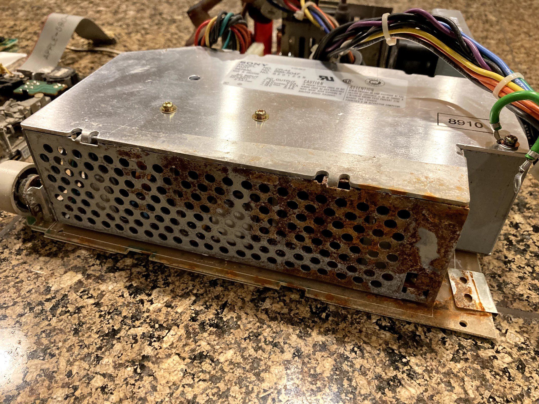
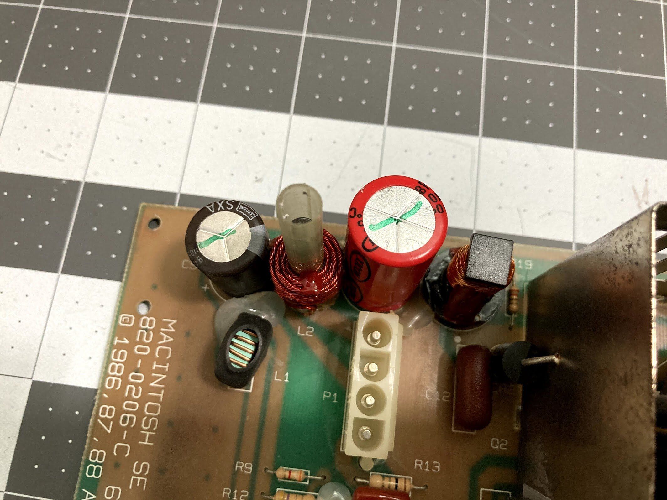
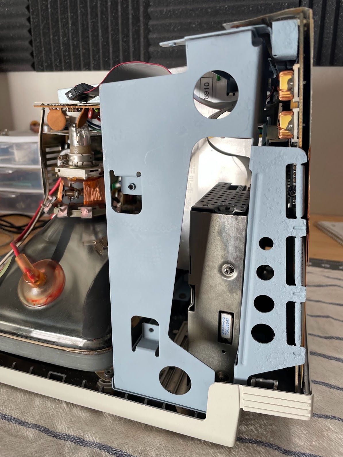
Let’s take a quick look at the rest of the parts. Here’s a closeup of the rust on the power supply. Next, I’ll be taking this apart to see how bad the damage is. I don’t think it’s as bad as the exterior suggests.
I won’t bother to fix this until we’ve verified that the machine will power on and read an external floppy, but I’ll have to clean up the floppy drive as well. Remember that this is a Macintosh SE FDHD, so this is a SuperDrive that can read 1.44mb disks! Worth saving for sure. The good news is that at this stage, I found that everything seemed to move okay, including the spindle and motor.
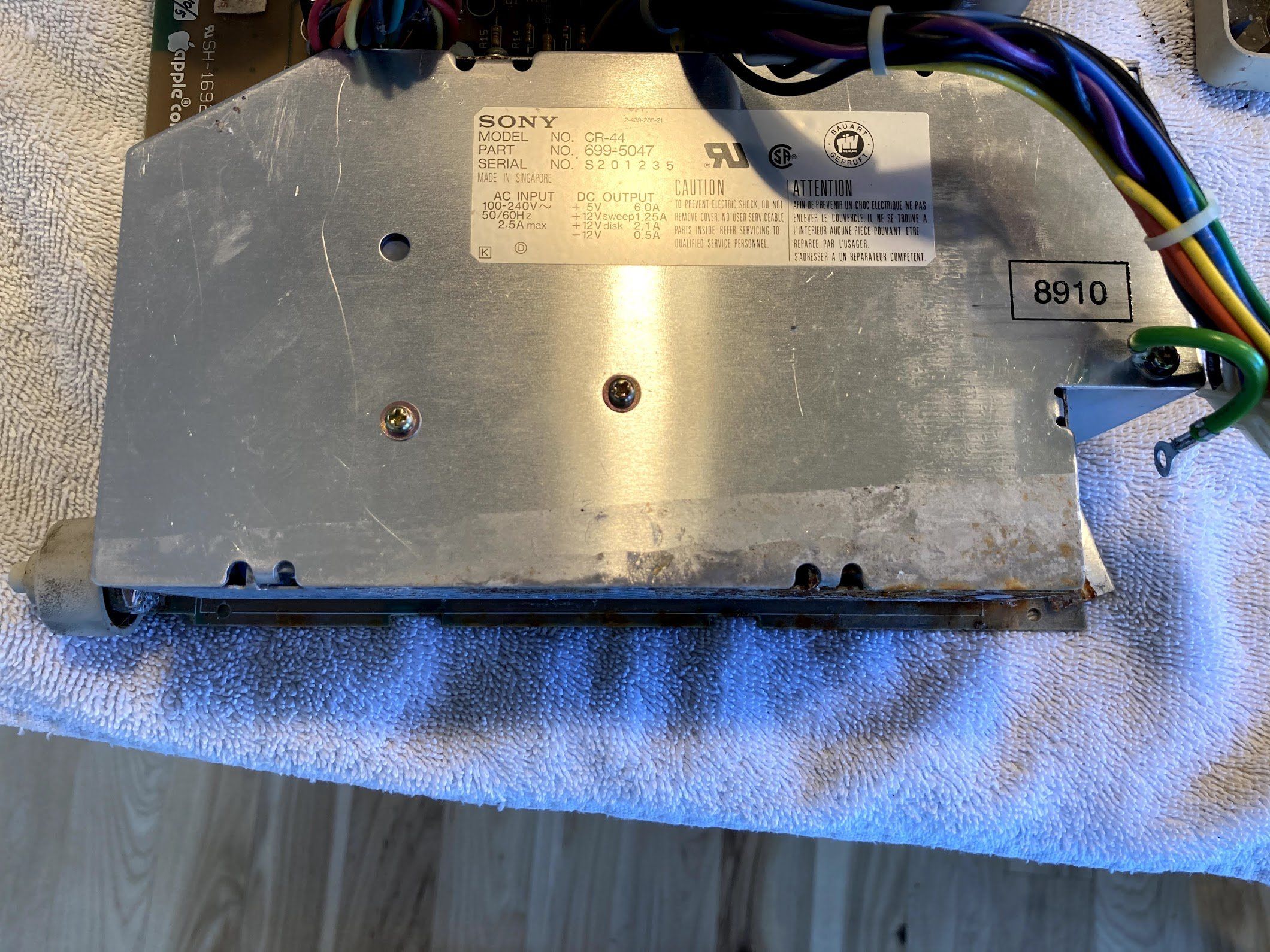
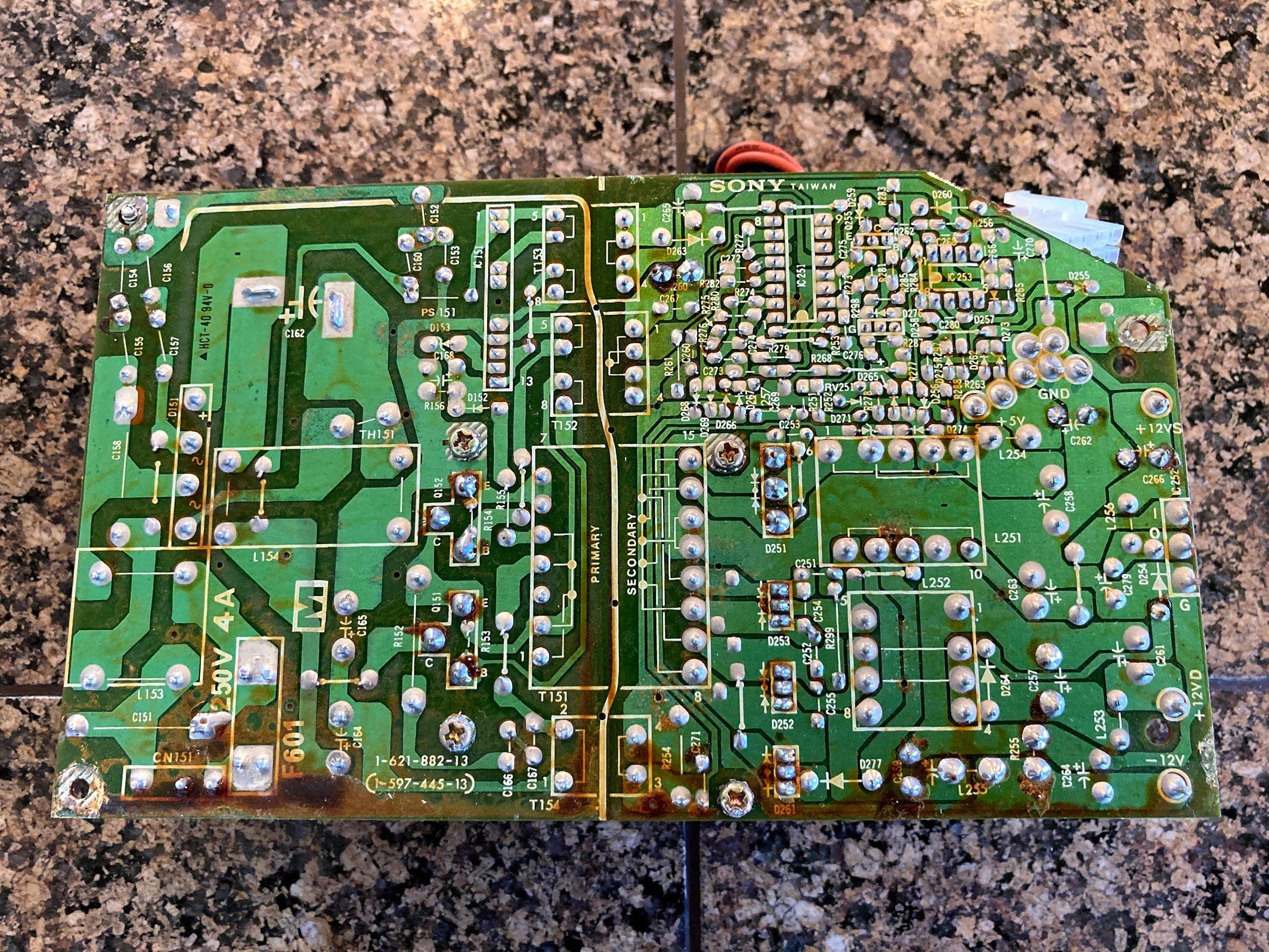
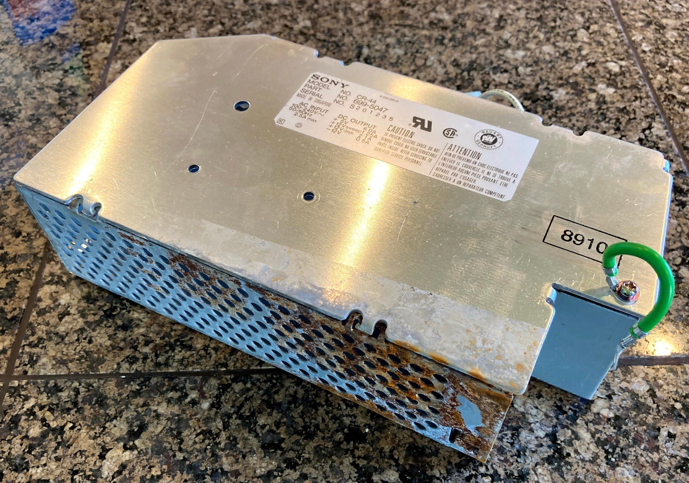
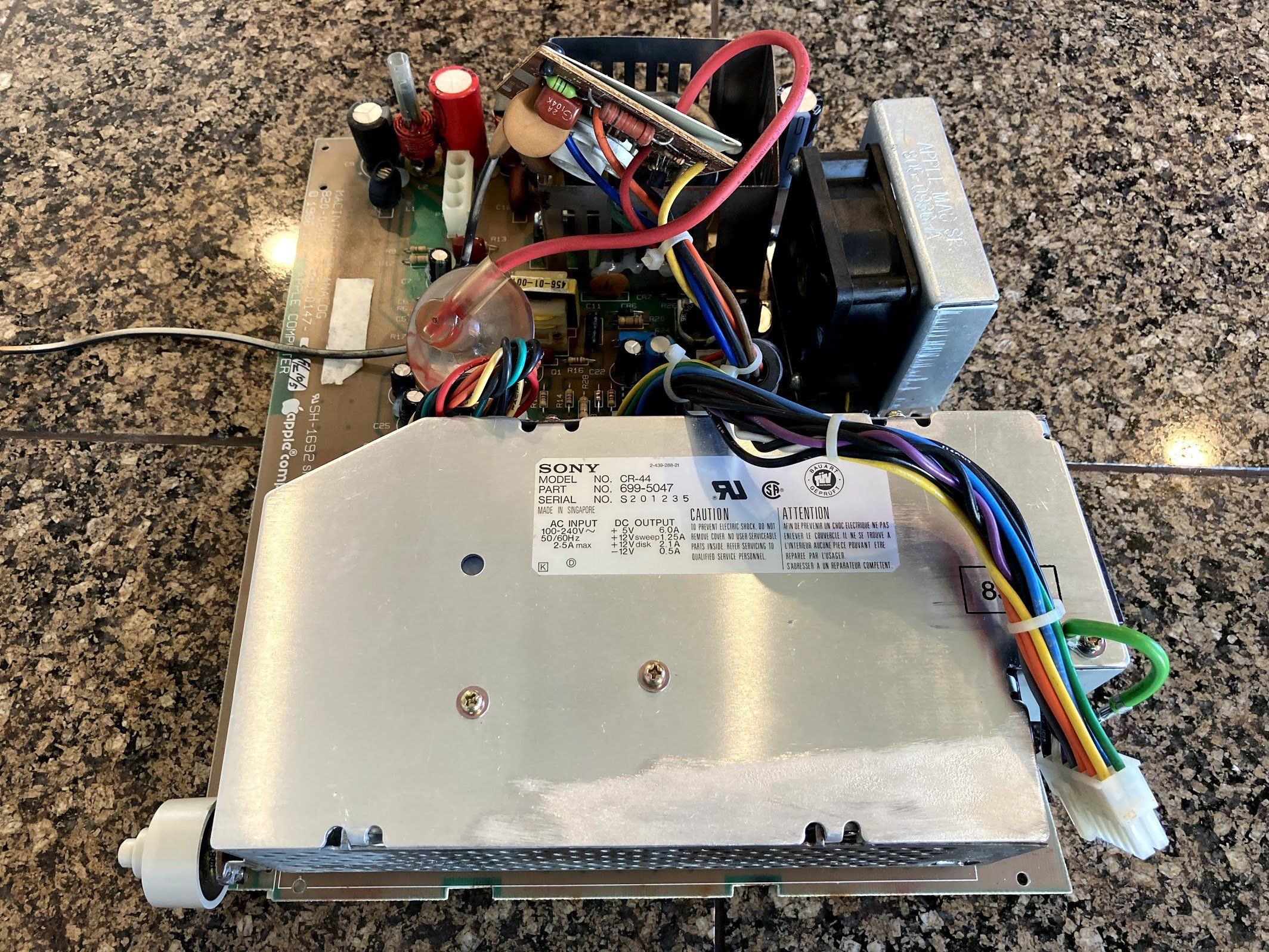
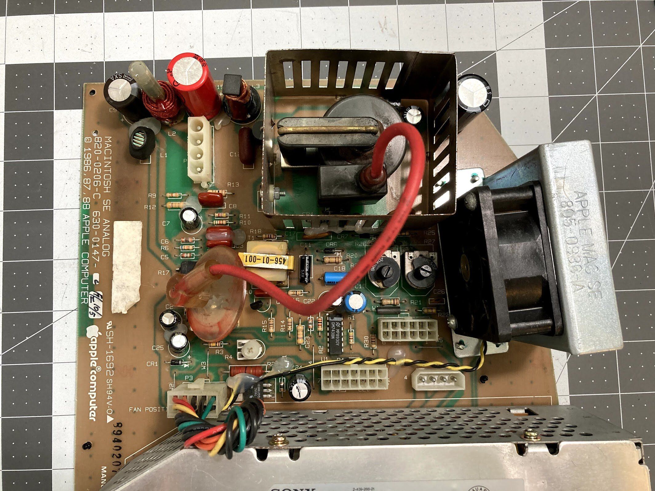
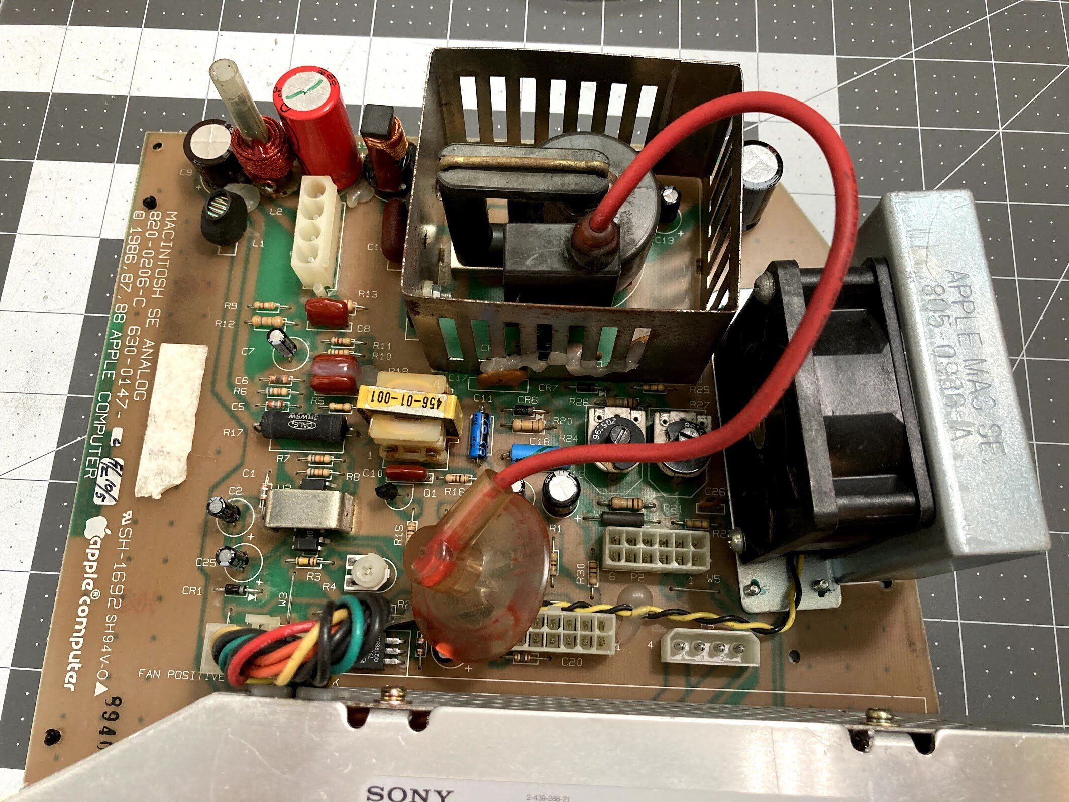
Let’s tackle the analog board and power supply! First, I cracked the lid on the power supply, which is a Sony model. Inside, it wasn’t nearly as bad as it looked. The enclosure was rusted, but the board and components looked okay.
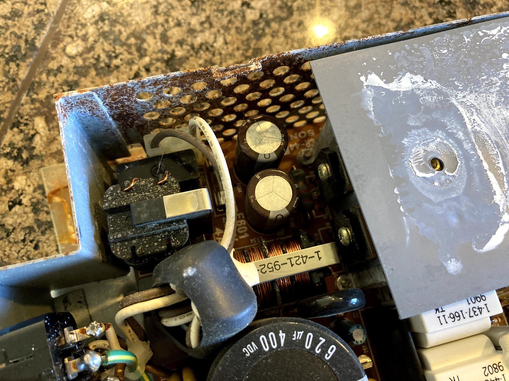
I removed the plastic shield on the back of the analog board, and found that it looked okay. A bit of corrosion but nothing serious, I’ve seen worse from capacitor damage. I used my impact driver to remove the four Phillips screws holding the power supply to the analog board.
With the power supply removed, I could see that the front of the analog board had some rust stuck to it.
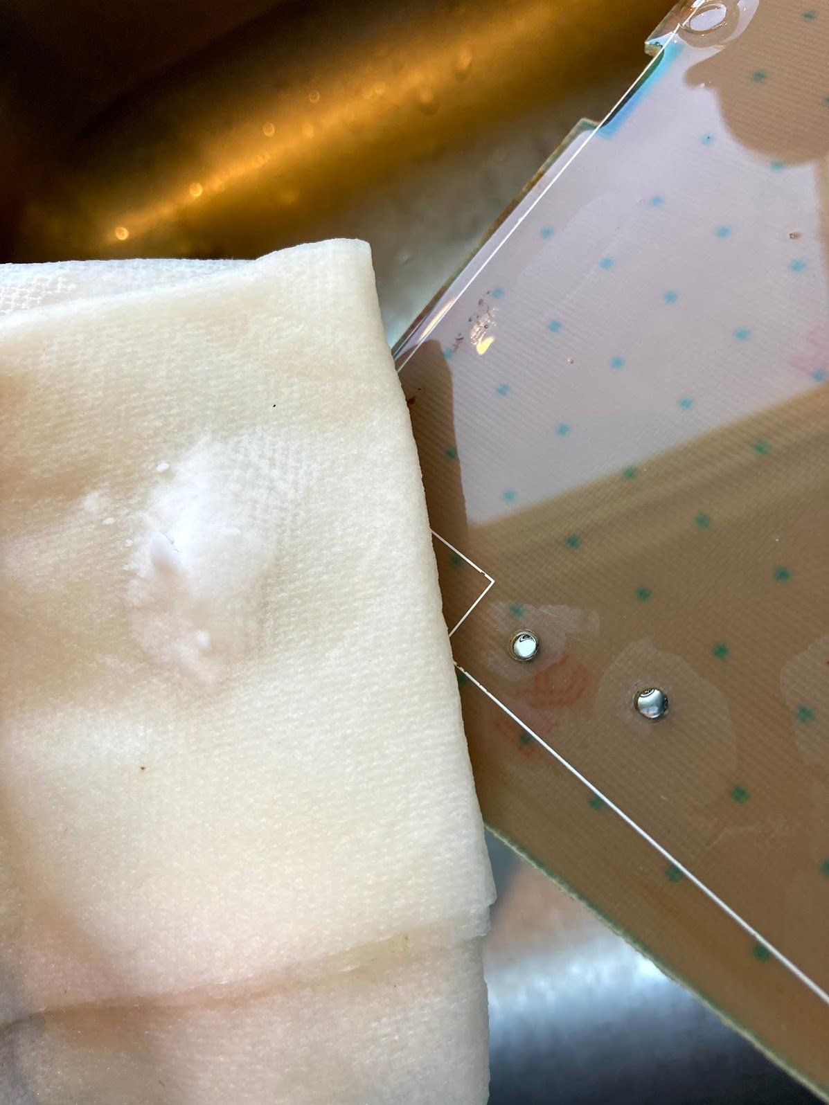
I took it to the kitchen sink to work on it. I started with soap and water and a toothbrush, and then I used baking soda on a wet paper towel to remove the last of it.
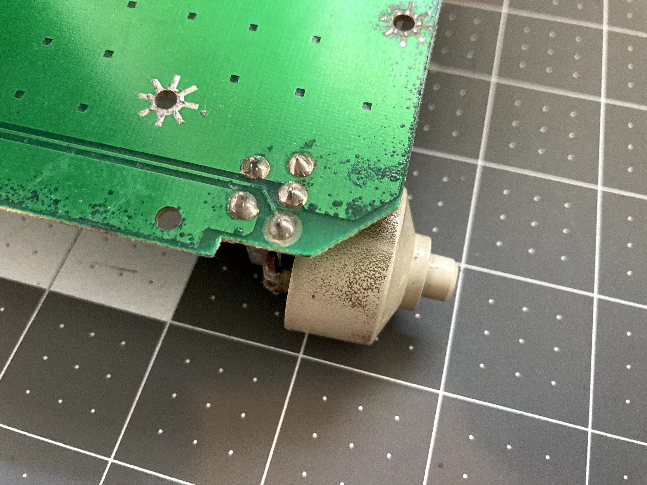
Since the analog board is out of the machine, I decided to clean up the brightness knob. In the past, my own SE FDHD had a faulty brightness knob that was erratic, and would only turn up to a certain brightness. I spent ages replacing parts on the board before finally just desoldering the knob, and rinsing the potentiometer with alcohol.
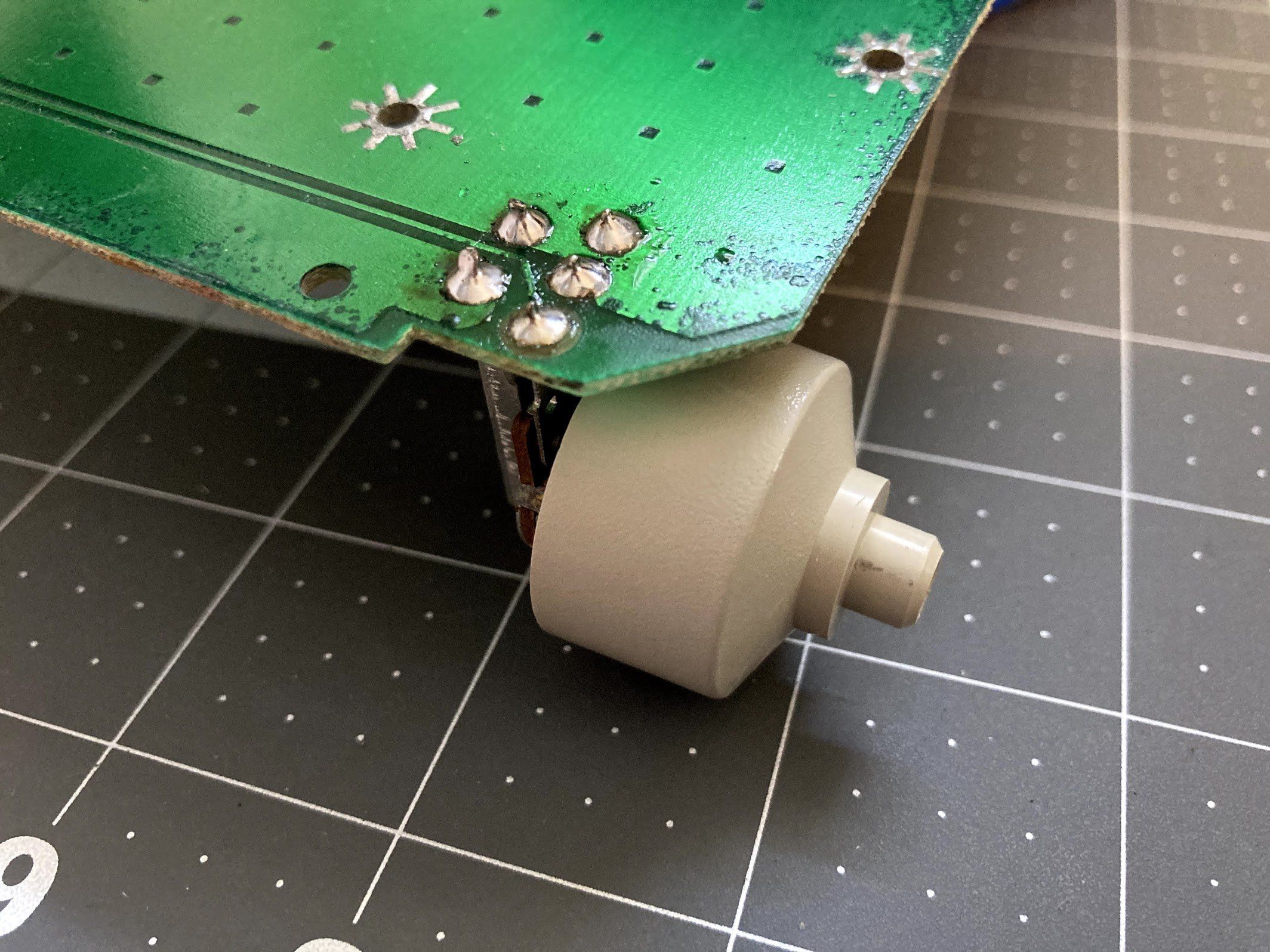
This one was literally under water, so I decided to do that here. Besides, it’s super gross on the outside and needs external cleaning anyway. Here it is with the original solder joints.
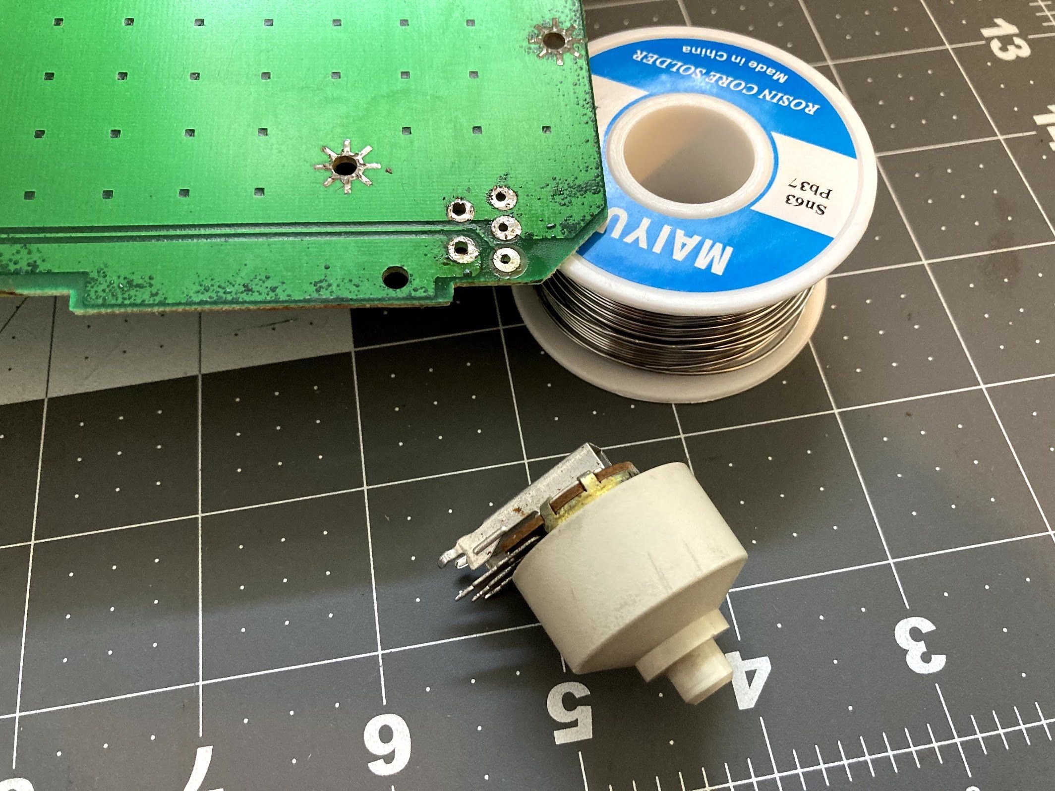
I heated my iron to 750°F, and attempted to heat one of the joints. No luck, so I tinned the tip with a bit of fresh solder, and instantly things started flowing. I used a cheap desoldering pump to remove the majority of the solder, then I followed up with a bit of desoldering braid to get the last bit. The knob popped right out.
I didn’t get photos of this part, but I went to the sink and scrubbed it with… you guessed it! Soap, water, and a toothbrush. When I was done cleaning the outside, I filled it up with alcohol, twisted it around a few times, and repeated once more. Then I took it back upstairs and reinstalled it.
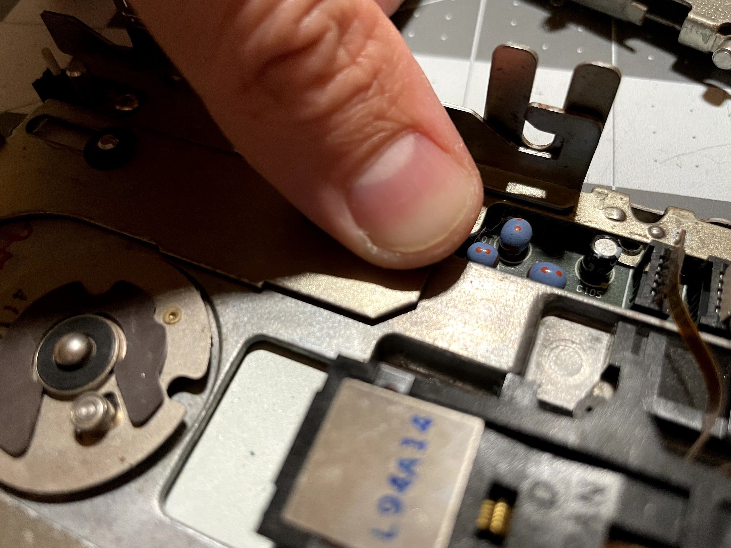
After that, the back of the logic board got a nice scrub with alcohol, and then a bunch of cleaning with the air compressor. I also used paper towels and alcohol to clean up the anode wire and cap. You’ll see them in a bit, they look brand new!
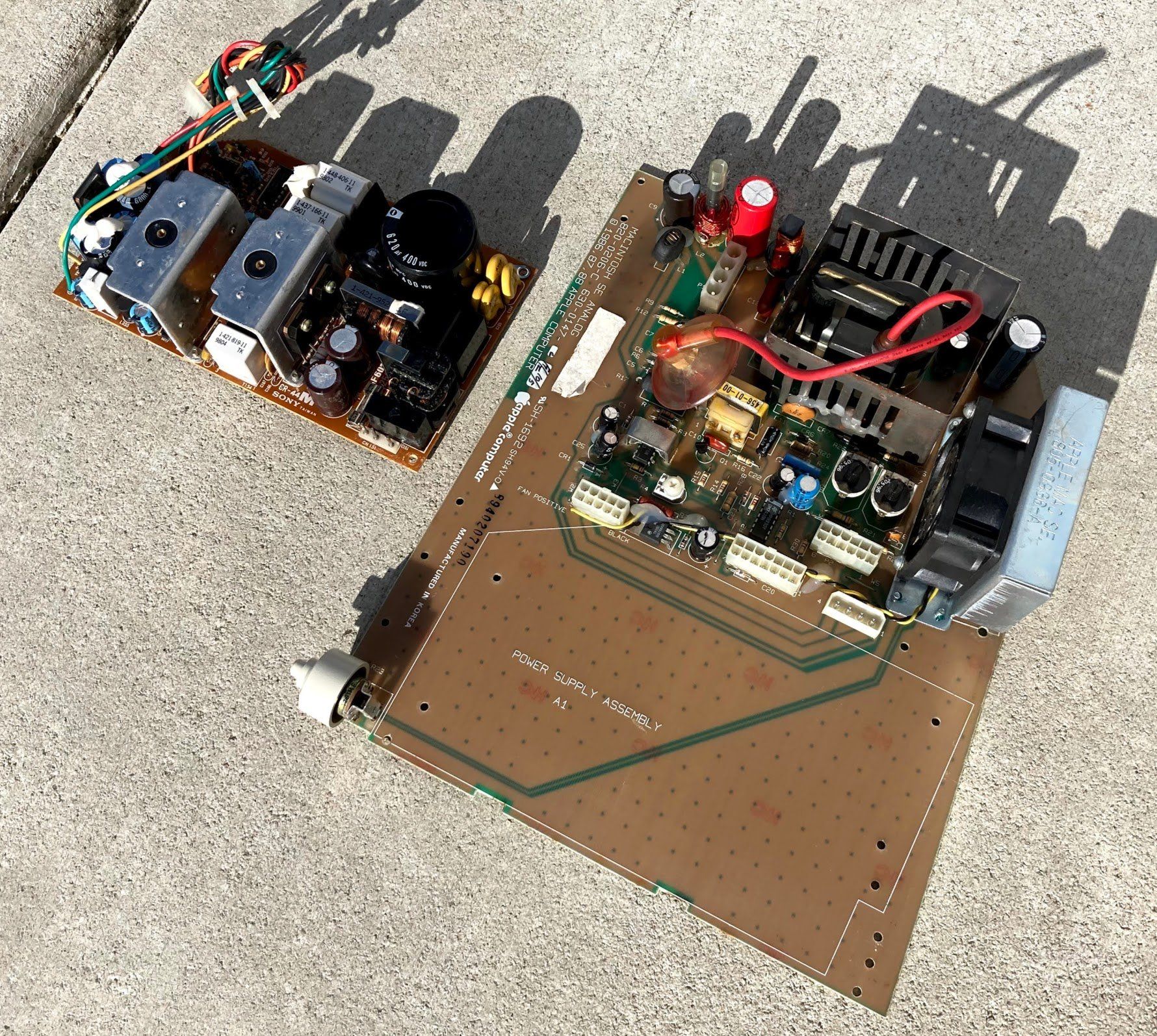
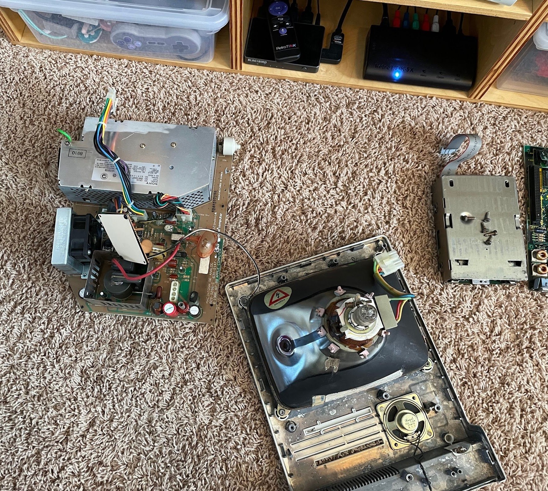
Power Supply
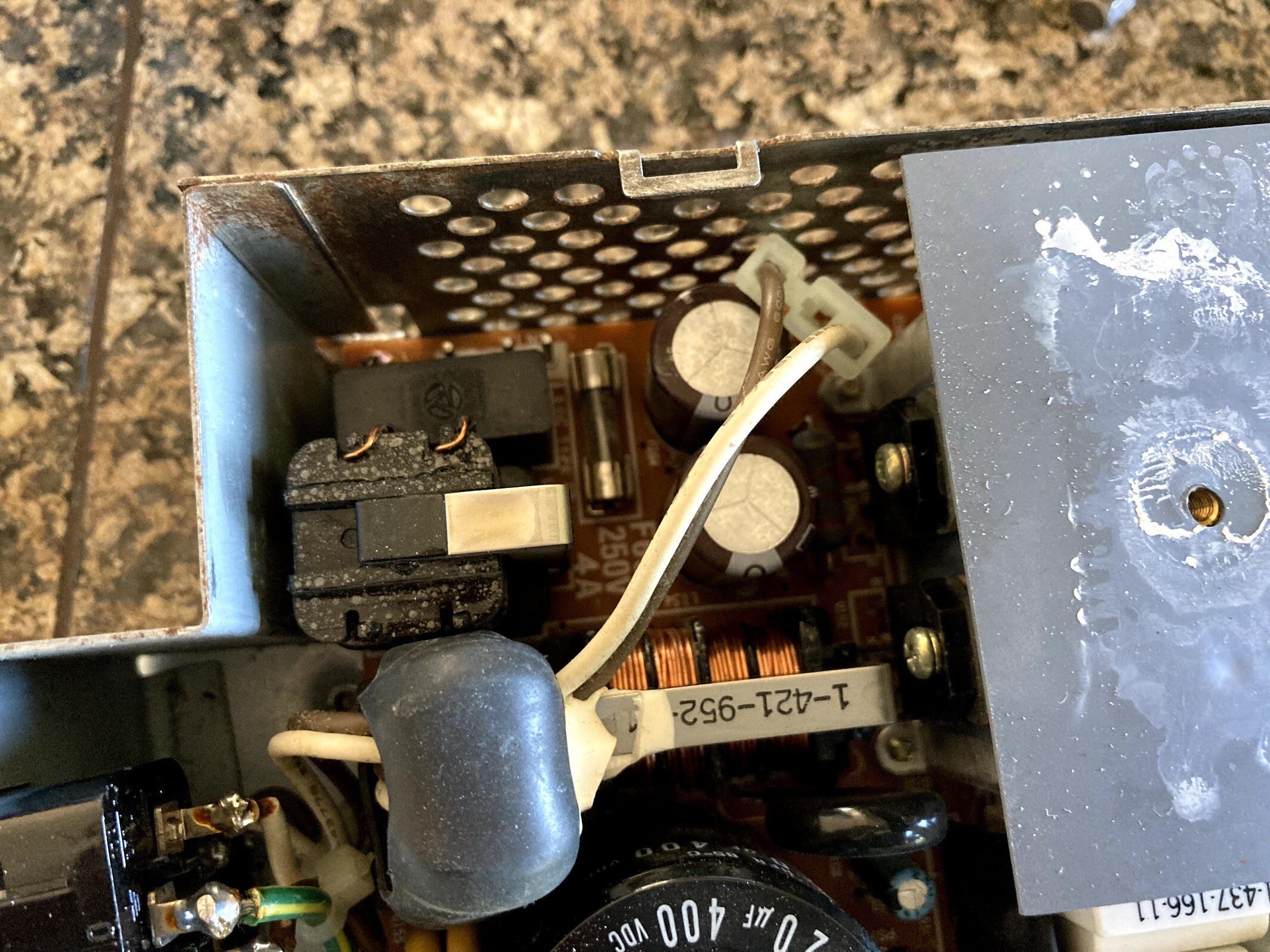
Next, I popped the power supply board out of it’s case. I somehow didn’t get an “after” photo, but here’s what the back of the power supply board looked like at first. It’s pretty easy to remove, just three Phillips screws, unclip the low voltage wire bundle, and sneak it out of the case. I’ve never recapped one of these because I was kinda afraid to get into it, but now I know that they’re pretty simple inside. An LC power supply is a lot more complicated to take apart and put back together.
All of the gunk that you see on the back of the power supply doesn’t seem to be rust or corrosion, it’s all flux! I scrubbed at it with alcohol and a toothbrush, and in no time, my hands were super sticky! I ended up scrubbing it several times with alcohol, scrubbing it with soap and water to remove the last bit, and blowing all of the moisture with the air compressor. Then, I put both the power supply board and analog board out in the evening sun to dry.
Also, check out that shiny anode cap!
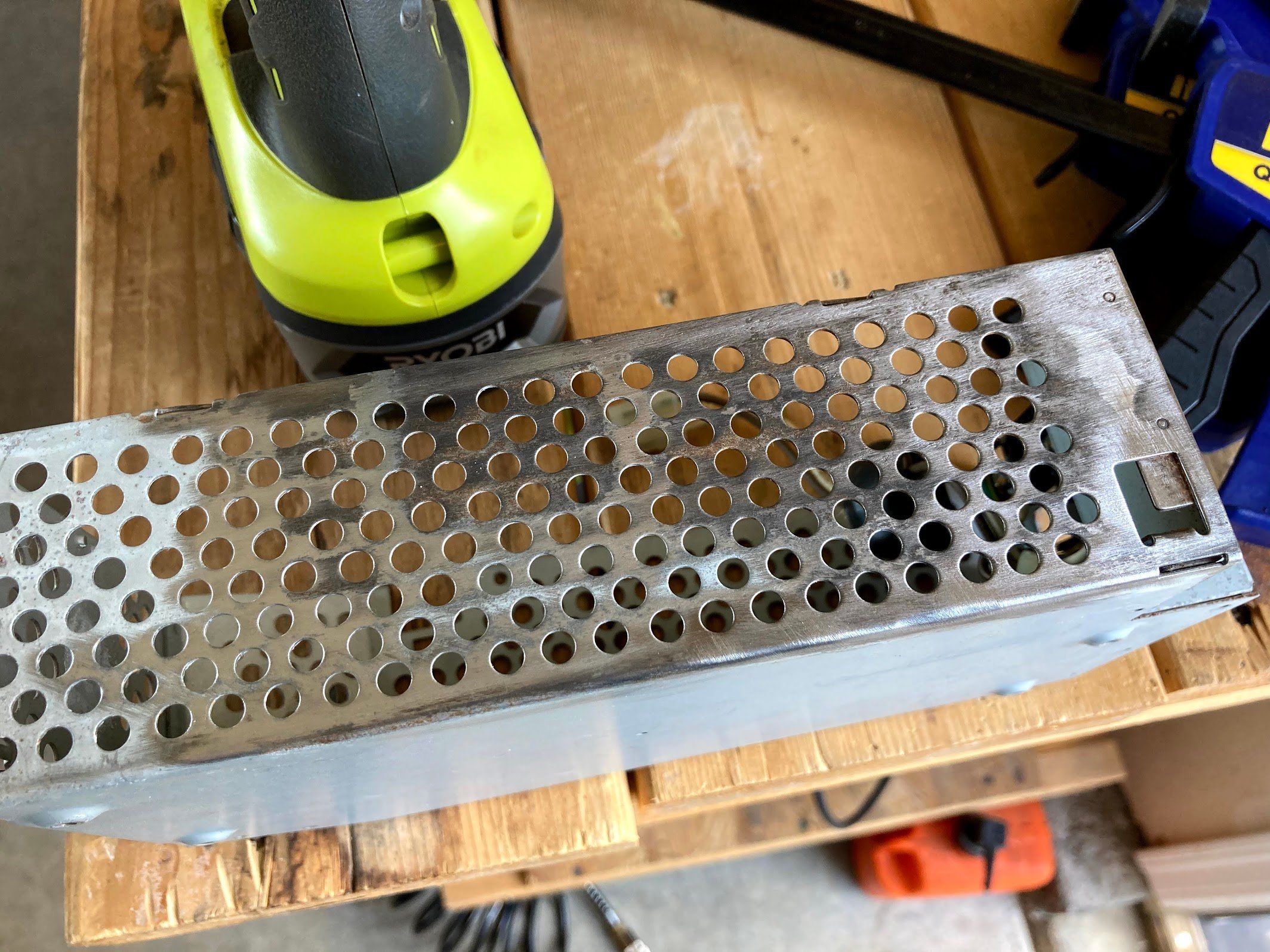
Next, I decided to work on removing the corrosion from the power supply case.
I took it out to the work bench, and used a couple of clamps to keep it still while I wire brushed it. It came out looking great.
I might need to paint the part of it that is bare metal later, but for now, I decided to put it back together to get closer to testing. I know that looks like a glass of whiskey in the background, but it’s just vinegar with some rusty screws in it.
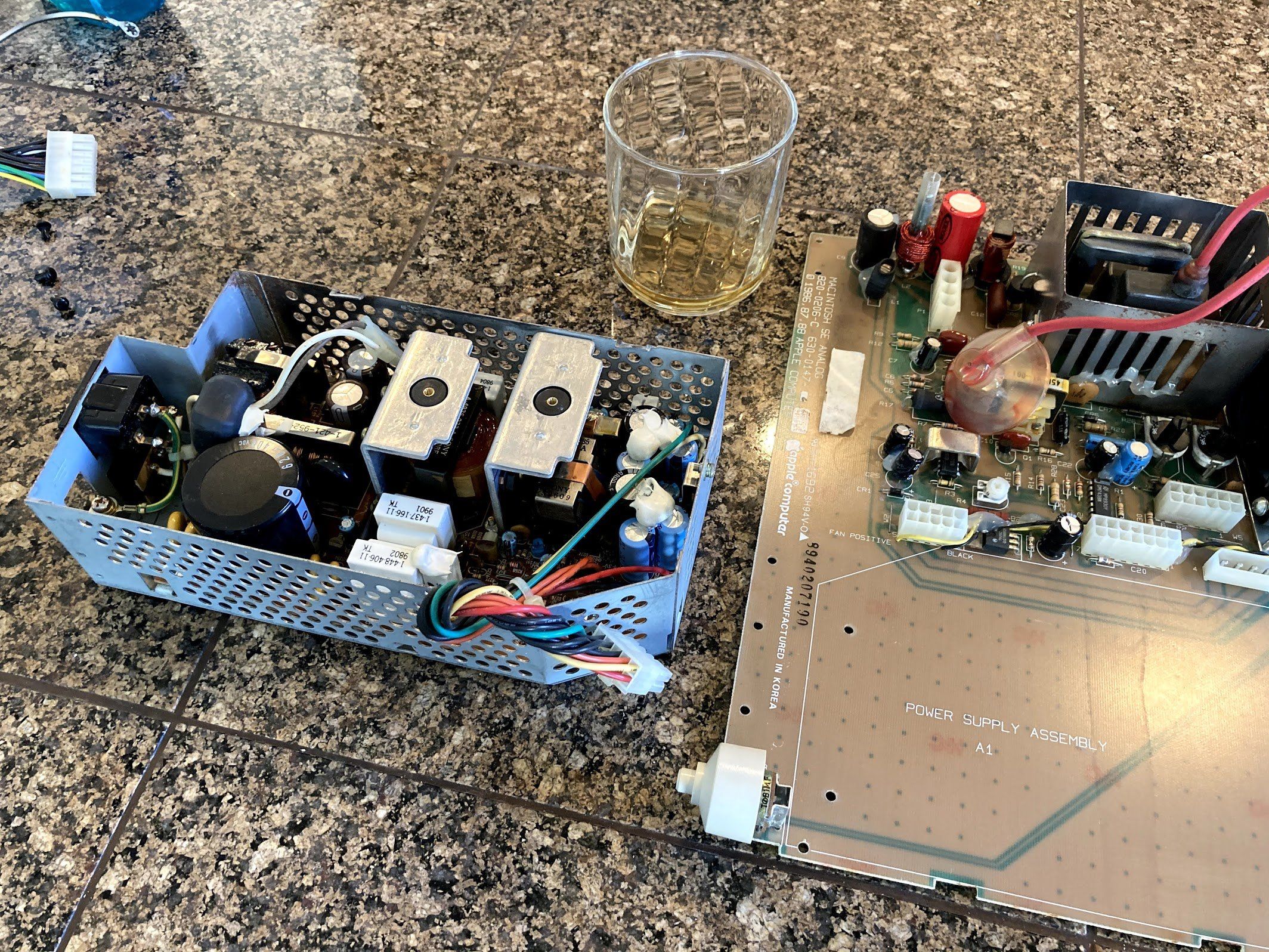
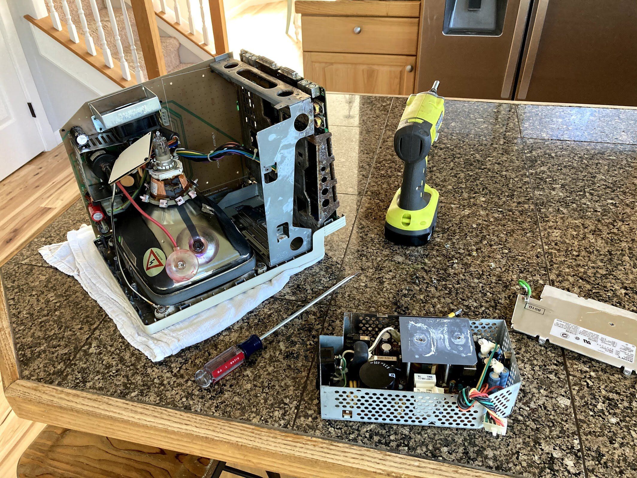
At this point, the power supply and logic board were reassembled!
There’s room for improvement here…
Windex fixes everything!
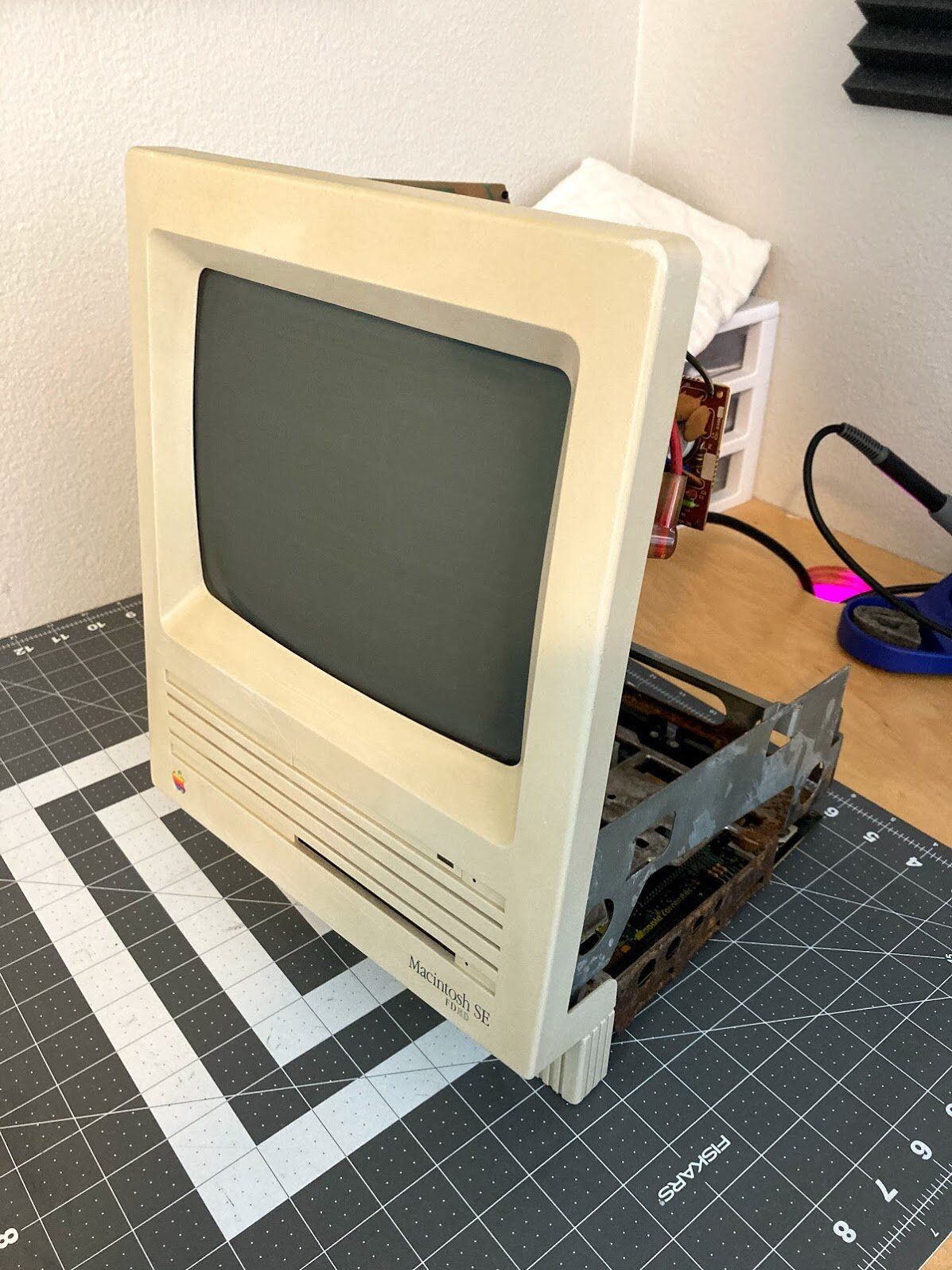
I reassembled the Mac, and I gotta say… it looks pretty insanely different then when I took it apart.

At this point, it was ready to test. I’m decided to wait until the next day to give all of the components to dry out; I wanted to give this Mac every opportunity to start up on the first try. Here’s a closer look at the internals:

At this point, here’s what was left:
- See if this thing even works! I’ll just use an external floppy drive for now.
- Functionality test including all I/O ports
- Clean, lubricate, install and test floppy drive
- Install and test hard drive
- Fix any analog board issues such as capacitors and screen adjustment
- Tear down
- Sandblast and paint chassis and brackets
- Finish cleaning up case bucket
- Retrobrite entire case
- Final reassembly
…you know. Assuming it ever works again.
The Moment of Truth
After the partial reassembly, I let the machine sit all night and all day while I worked. When work was done, it was finally time for the moment of truth! I plugged it in all by itself with no peripherals, and then flipped the power switch…
Nothing. Total silence. No activity whatsoever. Well, I guess expecting this to power on after it had been through was probably a bit too much to ask, huh?
But then I got to thinking. Maybe, just maybe.
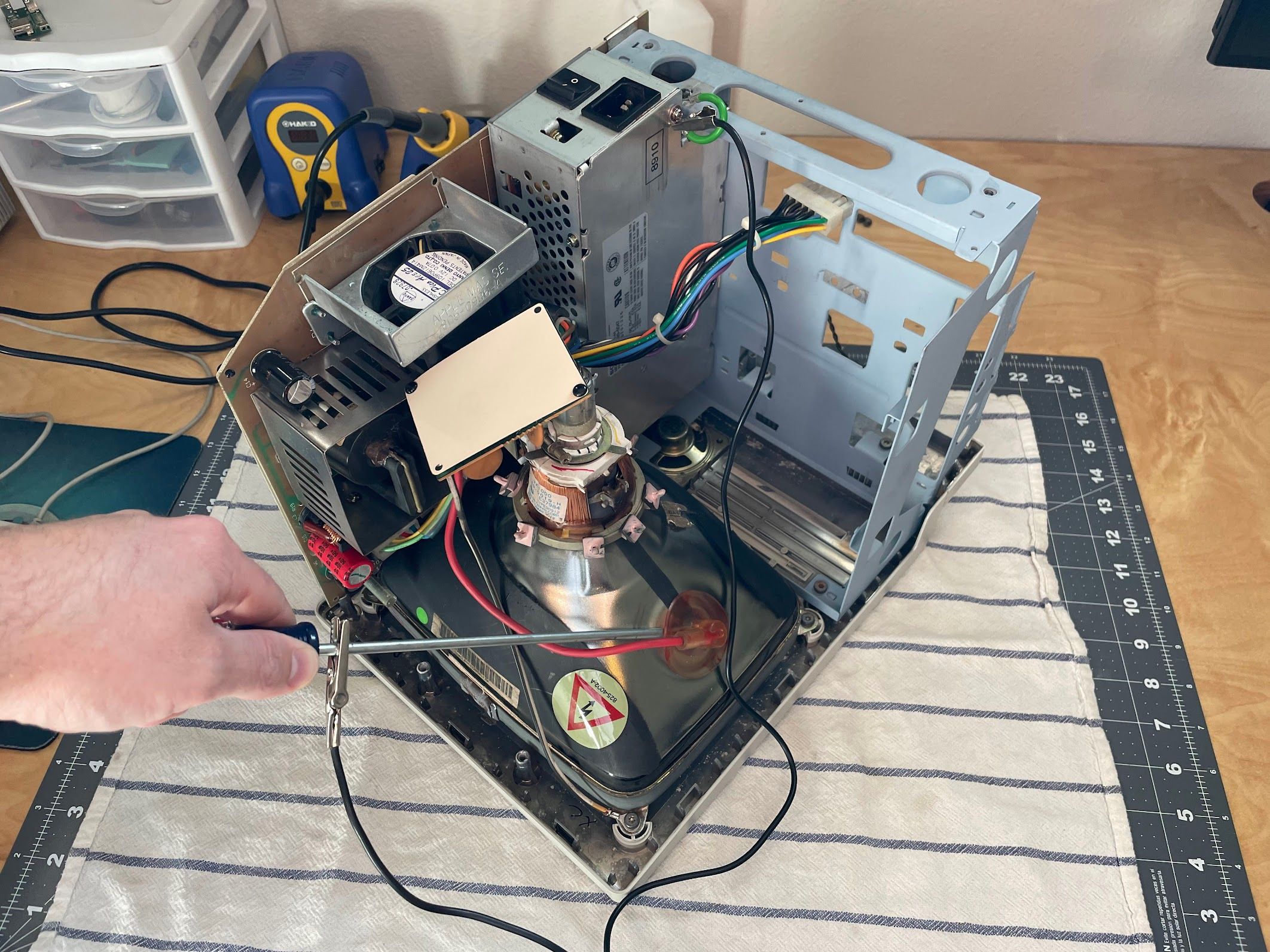
I removed the two screws near the back of the analog board that connect it to the chassis, and then the four screws holding in the power supply. Using a long screwdriver, is pushed in the locking tab on the power supply to analog board connector and popped it out. Then, I was able to twist the PSU sideways and sneak it out of the chassis, since the analog board wasn’t connected by those two screws, allowing the chassis to flex a bit. I put a bit of pressure on the CRT when I did this… probably not something I would do all of the time, but I needed to know.
Yep, there’s the problem!
That probably needs to be plugged in for anything to work! I plugged it back in, and hastily reassembled the machine.
The moment of truth. I flipped the power switch, and…
What?!

YES! It works! I could hardly believe it!
Next, I grabbed my external drive (which has a 1.44mb SuperDrive installed) and a System 7.0.1 Install 1 disk. I couldn’t find my Disk Tools disk, but whatever, I just wanted to see if the floppy controller worked.
Floppy controller works! Next, I texted my friend, who gave me the machine.
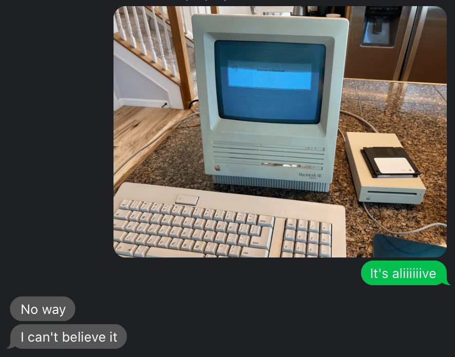
Neither can I! At this point, I’d verified that the external floppy port and both ADB ports work.
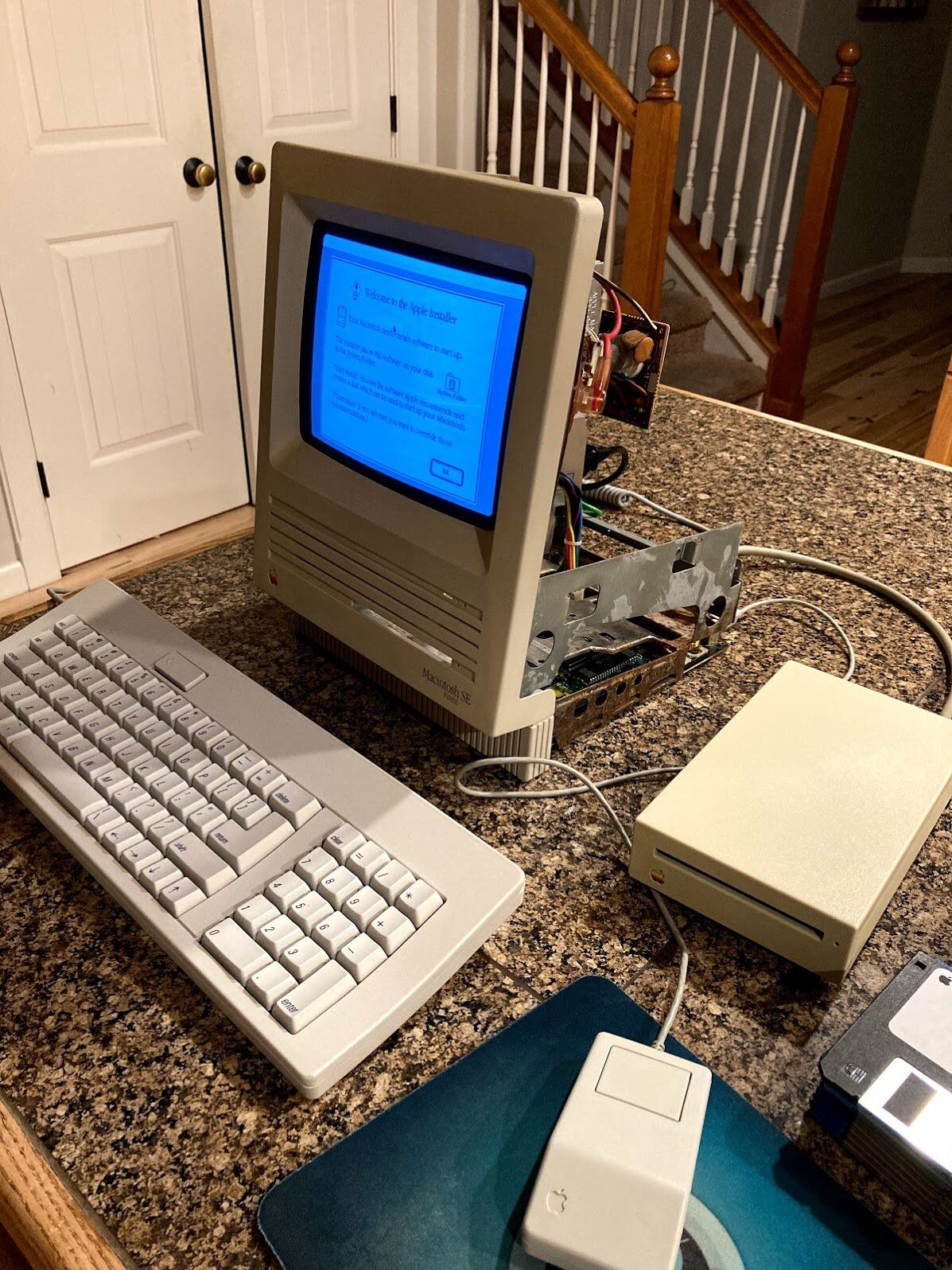
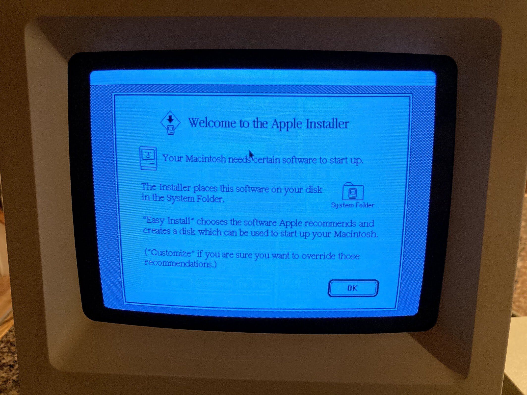
The screen was pretty dim (this picture was taken at night, in the daytime it’s a bit hard to see), so I adjusted the max brightness cutoff up as much as I could before lines appear. As you can see, there’s pretty severe burn-in; this CRT has a lot of hours on it, and is probably pretty tired.
But I didn’t care. It works! Of course, there was a lot left to do.
Retrobrite
At this stage, the machine could power on, boot from an external floppy drive, and had working ports all around. I decided to keep going and see what else I could improve. The case was clean, but I had some sunny and hot days coming up; the perfect opportunity for some retrobrite! While I did scrub the case down earlier, I didn’t really detail it. There are still some rust stains, black marks, and grimy corners to deal with. I discharged the CRT and disconnected the anode wire, and went to work with the impact driver. And speaking of the impact driver, I’ve been using it a LOT on this project. I think it will become a main part of how I work on these going forward. It makes teardowns super fast.

A couple of minutes later, it looked like this:
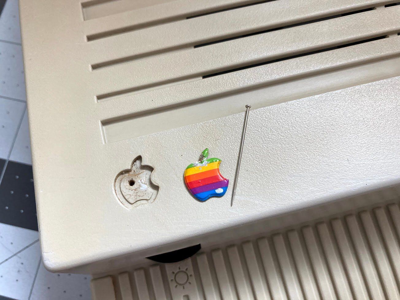
Before retrobrite in the sun, it’s important to remove the Apple badge. If not, the heat and direct sun can bleach out the red and yellow colors. To remove it, carefully push something through the hole in the back. Be careful though, something sharp like this needle can poke through the paint in the badge. No trouble here, but just something to watch for. Normally I use a paperclip but the hole was too small.
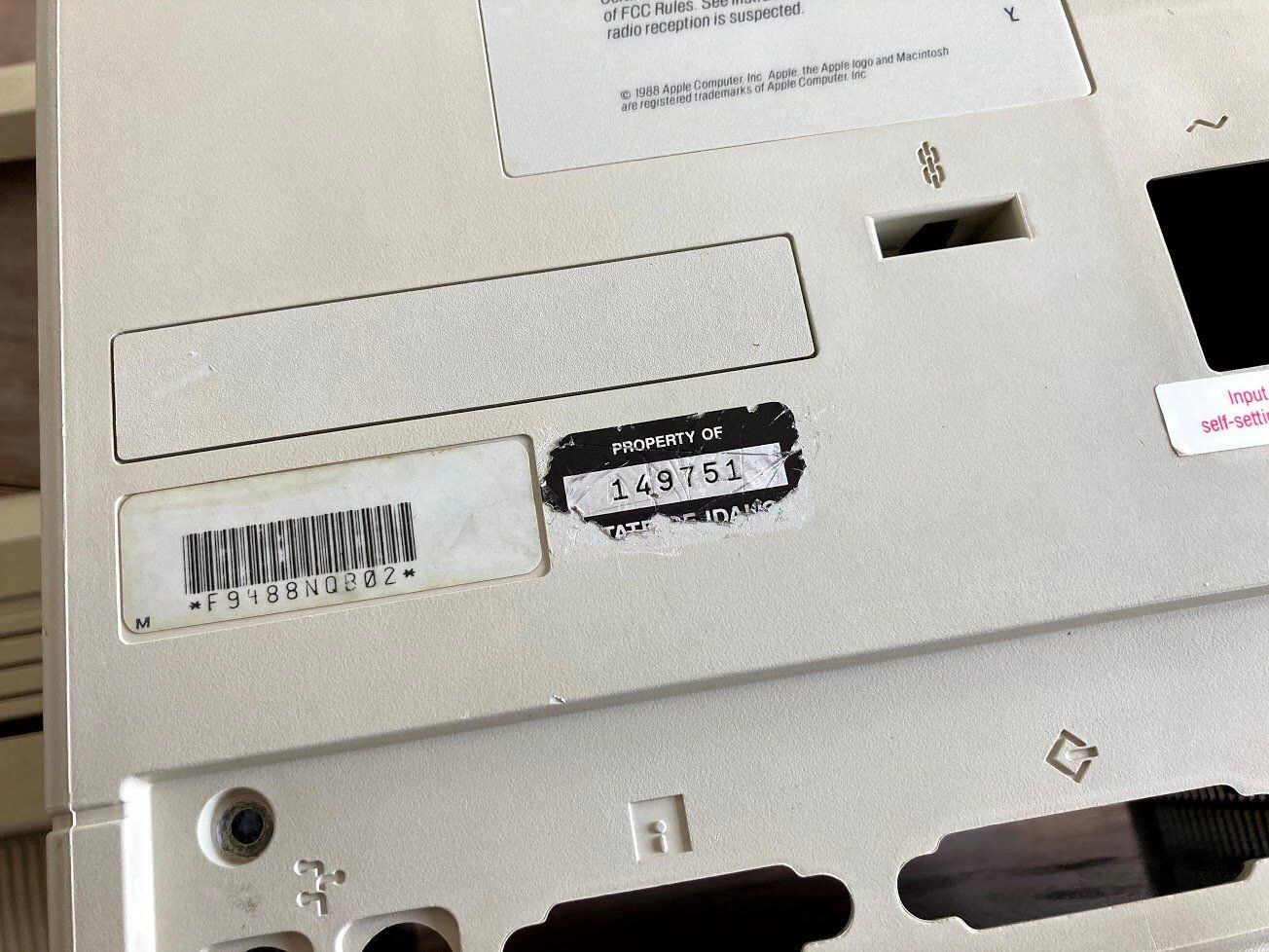
Next, it was time to remove this stubborn “Property of the State of Idaho” sticker. I see a LOT of these stickers - pretty much every Mac I’ve bought locally bears one. Unfortunately, this one is too damaged to leave on.
I carefully got under it with a razor blade.
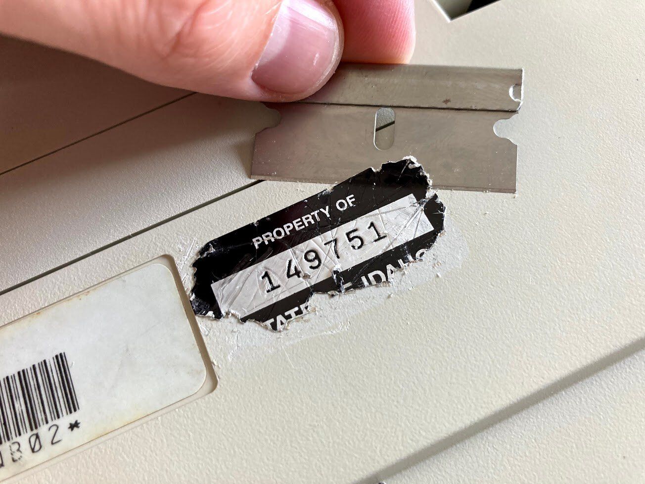
While I did cause a couple of new scratches, I think it was worth it.
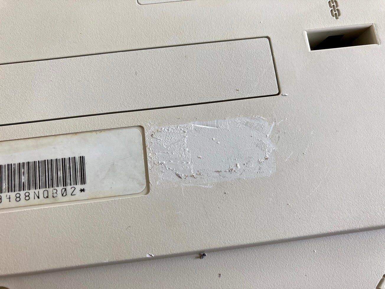
To finish removing the sticker, I attacked the residue with some Goo-Gone.
Deep Cleaning
With the sticker all taken care of, it was time to take the case outside for a final cleaning. I used my old standby: Dawn dishwasher detergent and a toothbrush.
For stubborn marks and scuffs, I used baking soda on a wet paper towel like before. There wasn’t a single surface on the Mac that didn’t need to work with the baking soda!
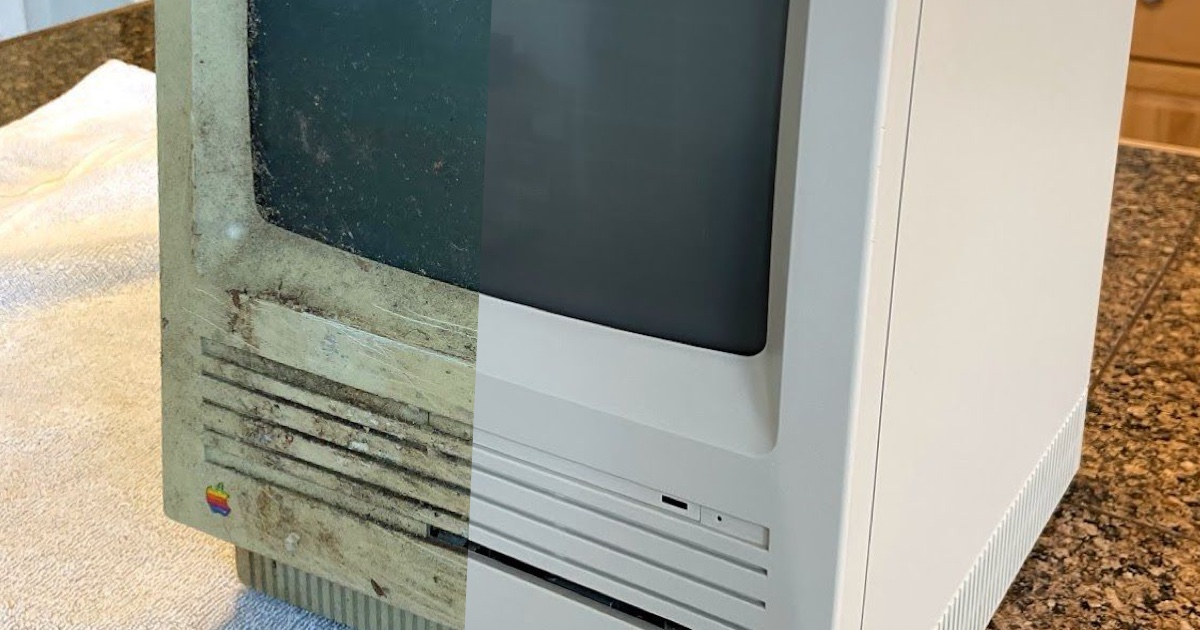
As a reminder, here’s what the rust stains looked like before I went crazy with baking soda:
And here’s what the Mac looked like after a good cleaning!
On the inside, there were still some rust stains…
Retrobrite
Time for retrobrite! Here’s what the Mac looked like at the beginning of the day.
To prepare, I left some water out in my clear Sterilite container overnight. In the morning at 9 or 10 AM, it was about 24°C (75°F). We want about 35°C (95°F), which is where the reaction starts to happen.
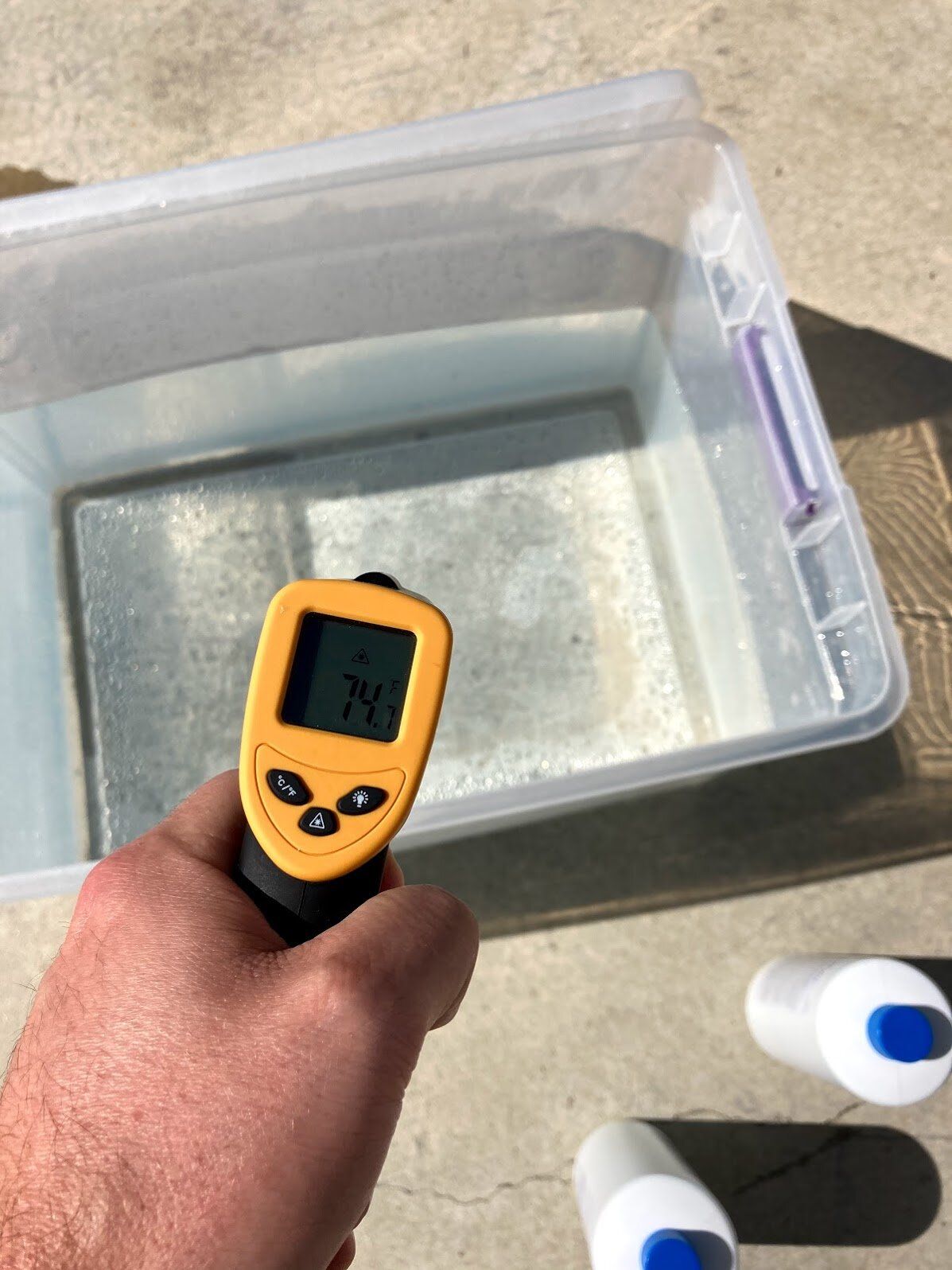
I dumped in about 6 bottles of 40-proof Hydrogen Peroxide. Normally, a couple would be fine, but the weather wasn’t co-operating; it didn’t look like it was going to be a very hot day. To help the problem, I added my $10 fish tank heater, which has a maximum temperature setting of about 35°C (95°F). The heater barely gets it hot enough for things to start happening, but it does help get the water up to temperature for the sun to take over and keep going.
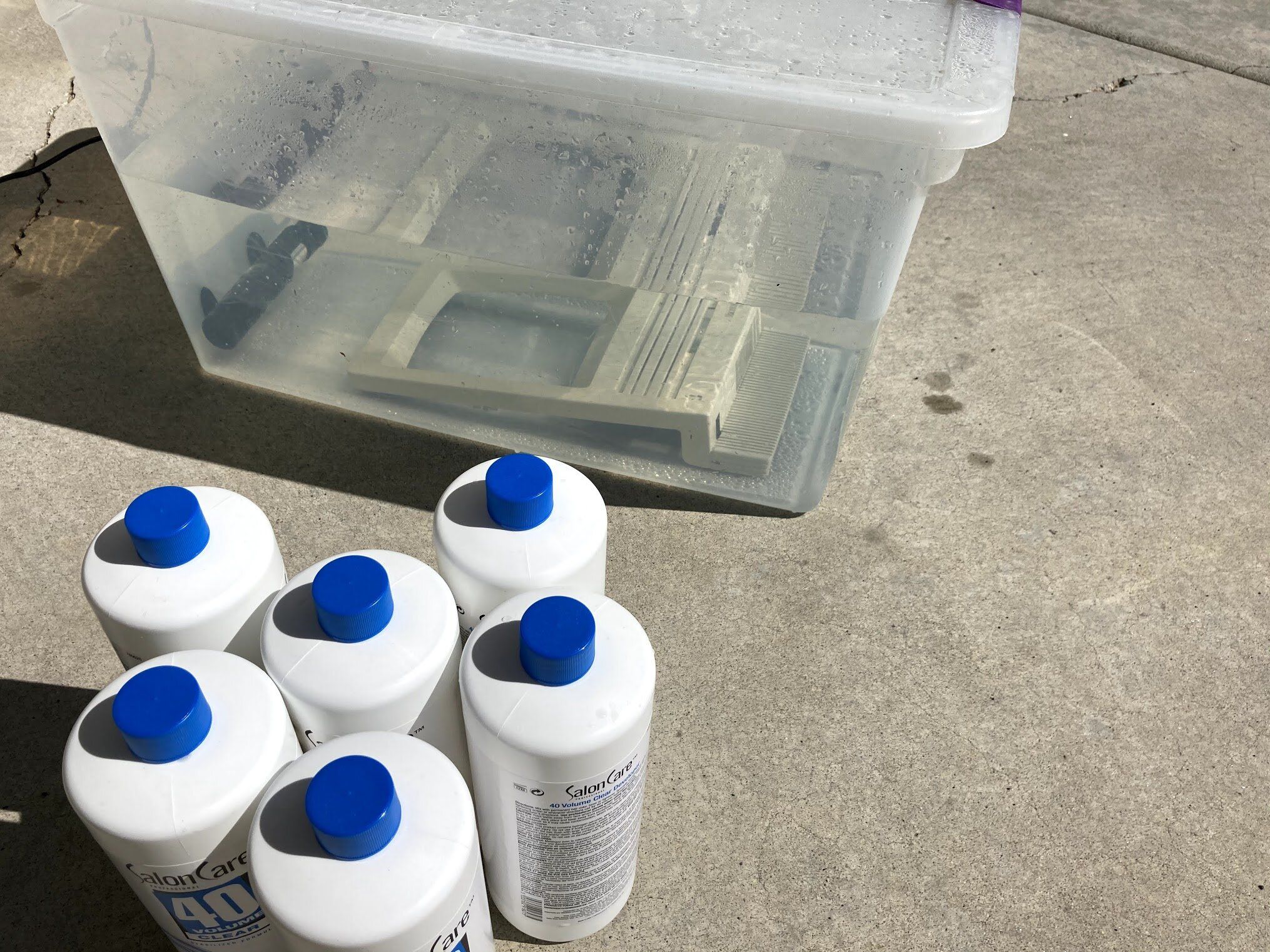
Sadly, it just didn’t end up getting very hot - the fish tank heater did the majority of the work, but it did seem to be working!
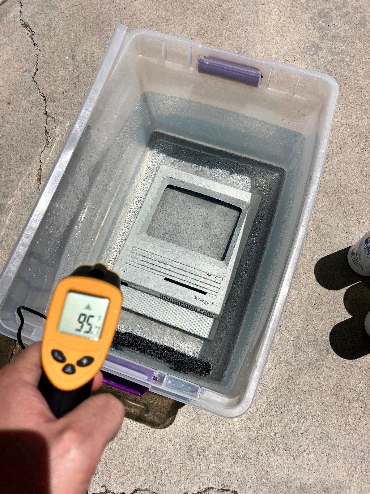
After about 4 hours, I swapped in the back, and left it in for the rest of the day.
Towards the end of the day, I took the rusty chassis and logic board shield over to my brother’s shop. He has a ton of great tools, like a sandblasting cabinet. I’ve never used one of these, and found that it’s pretty hard to see what you’re doing in the cabinet.
Here are the results. He instructed me to not touch the parts - just go home, hit them with compressed air, and apply primer.
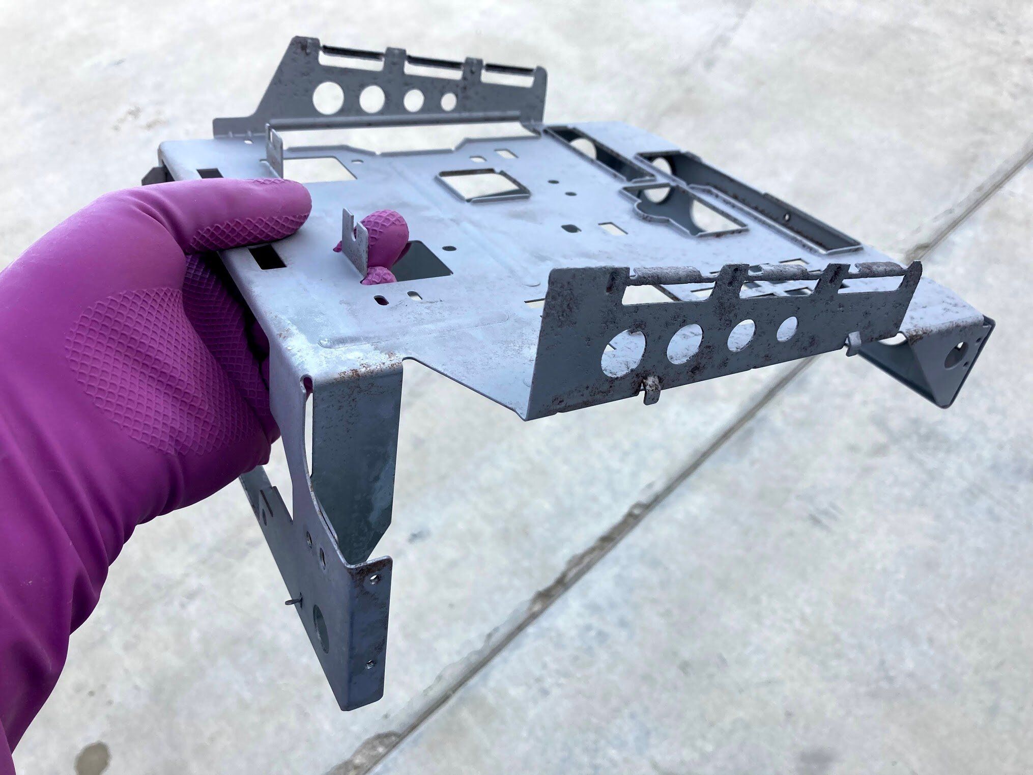
Keeping grounding in mind, I masked off a few things with tape, and hit the parts with some leftover engine primer that my brother gave me.
After a full day of retrobrite, even in the cooler weather, the parts were done. I think the high concentration of Hydrogen Peroxide, and the consistent 95°F from the fish tank heater did the job. Sadly, I didn’t snap a photo at this stage, so the satisfying reveal will have to wait a bit.
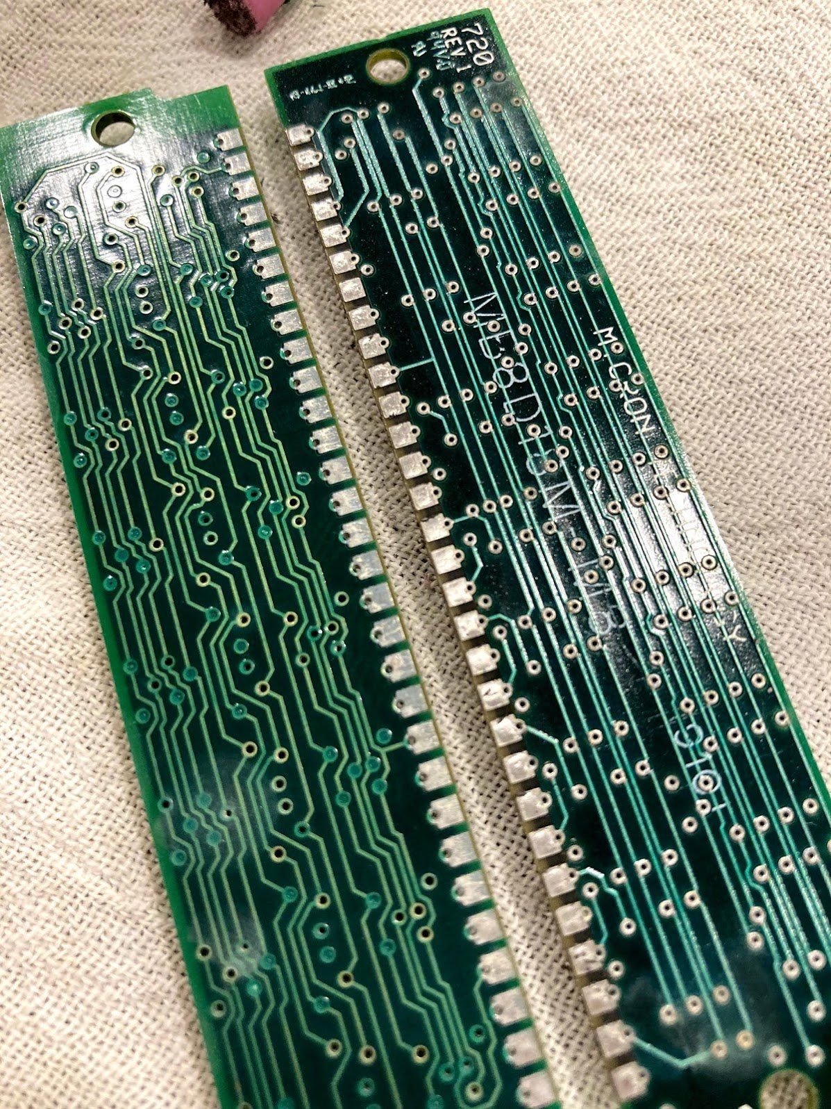
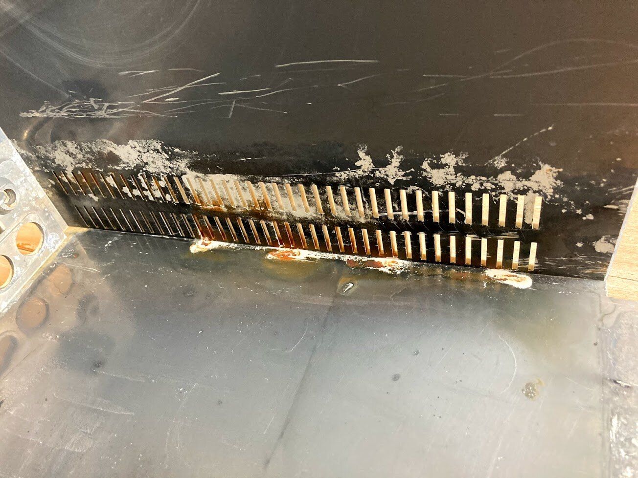
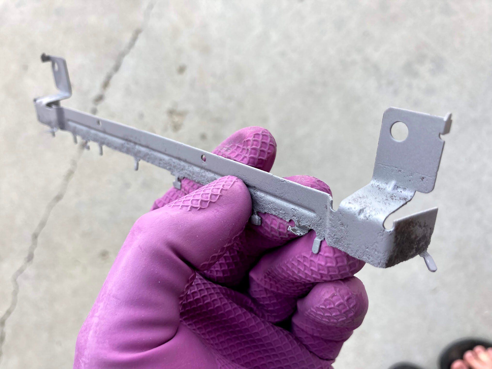
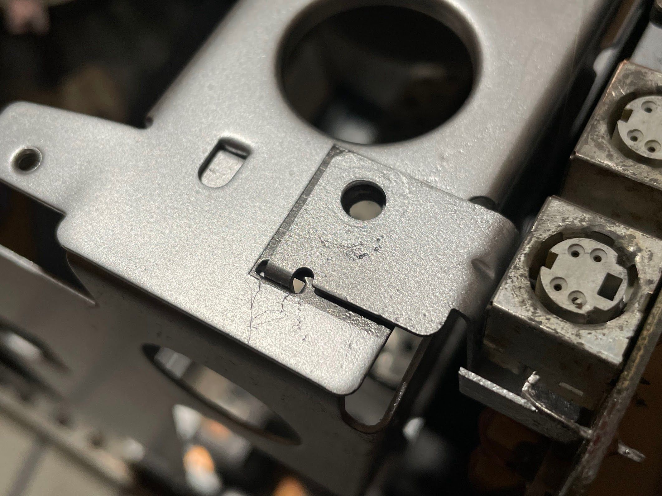
Logic Board Shield
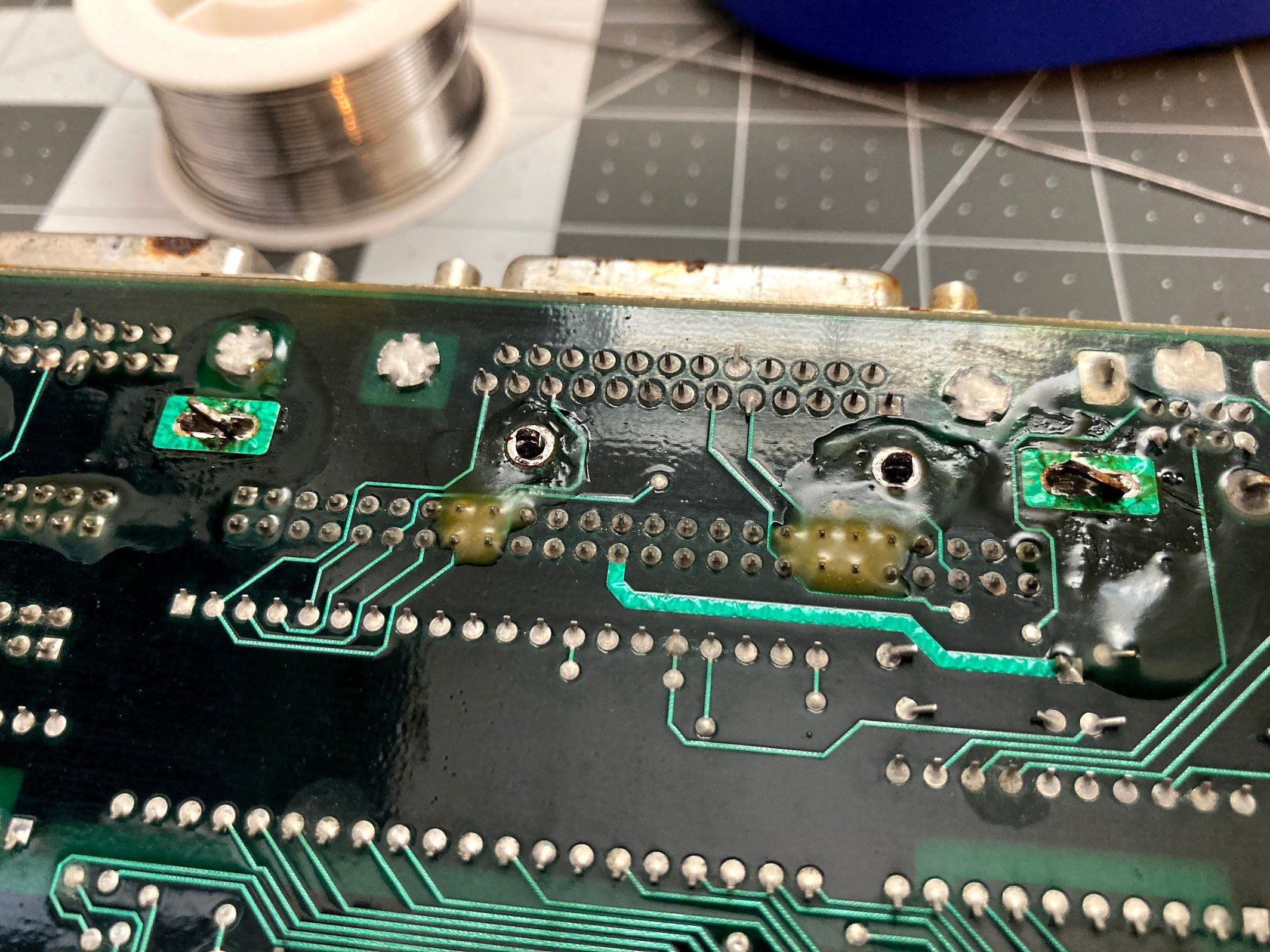
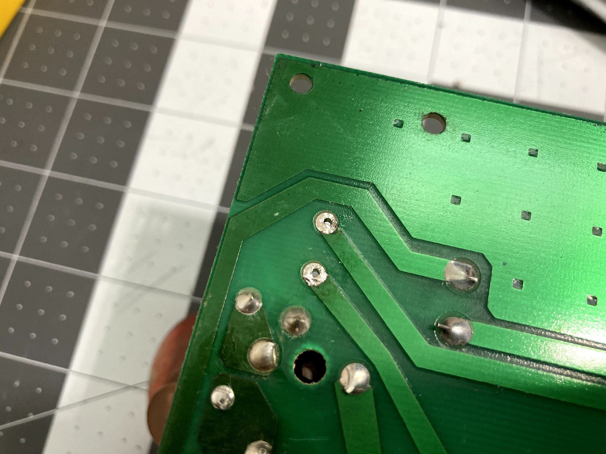
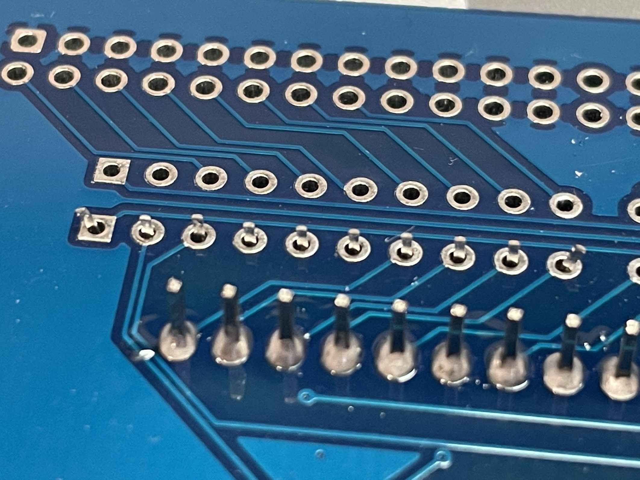
Before soldering the shield back onto the logic board, I decided to clean up the I/O ports a little bit. Here’s what they looked like before.

And here’s after working on them with some 1000-grit sandpaper. Much better!
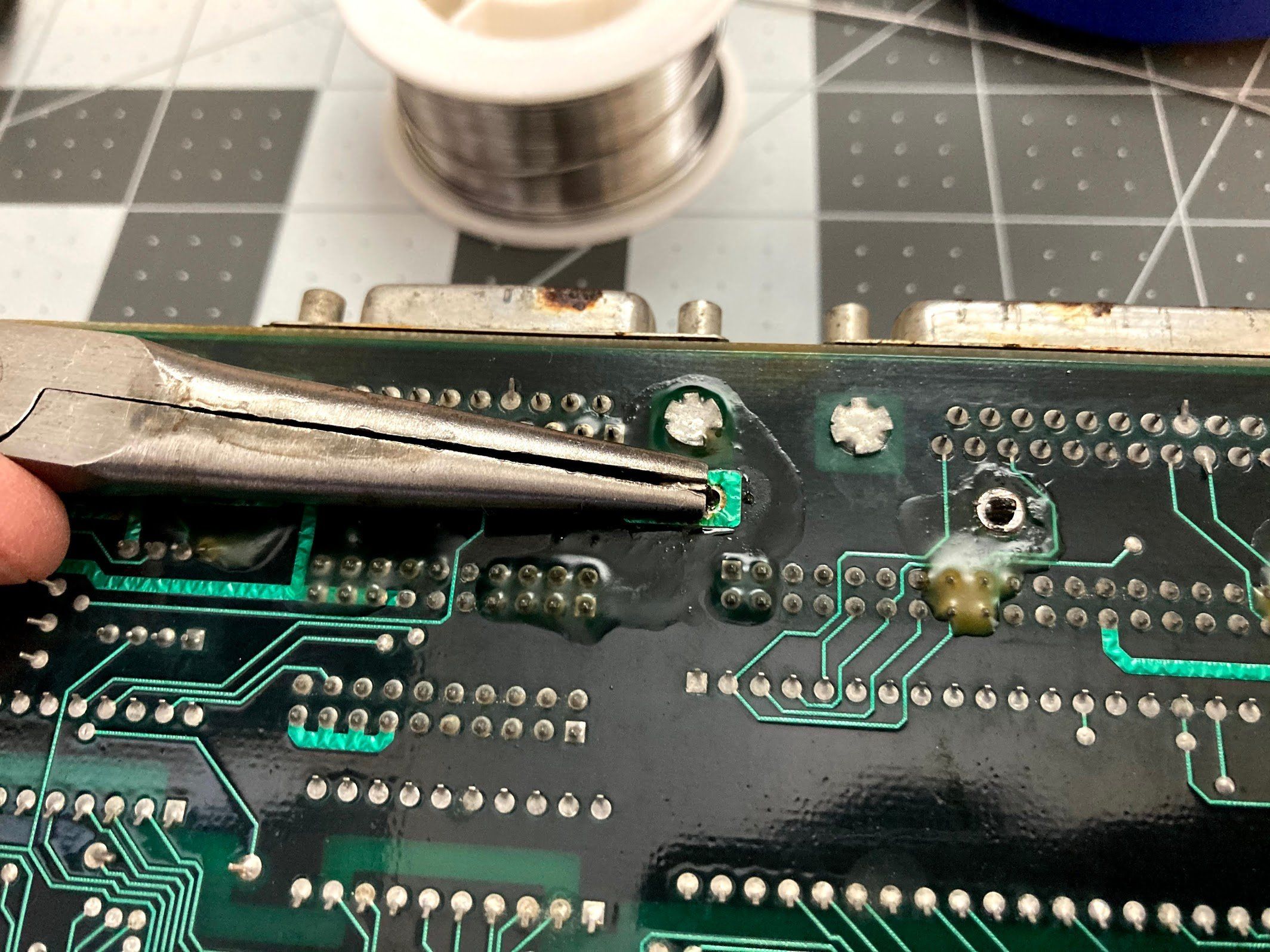
After slotting in the RF shield, I bent the tabs like they were before. It was pretty easy to solder the shield in since it was held in place.
Shield installed!
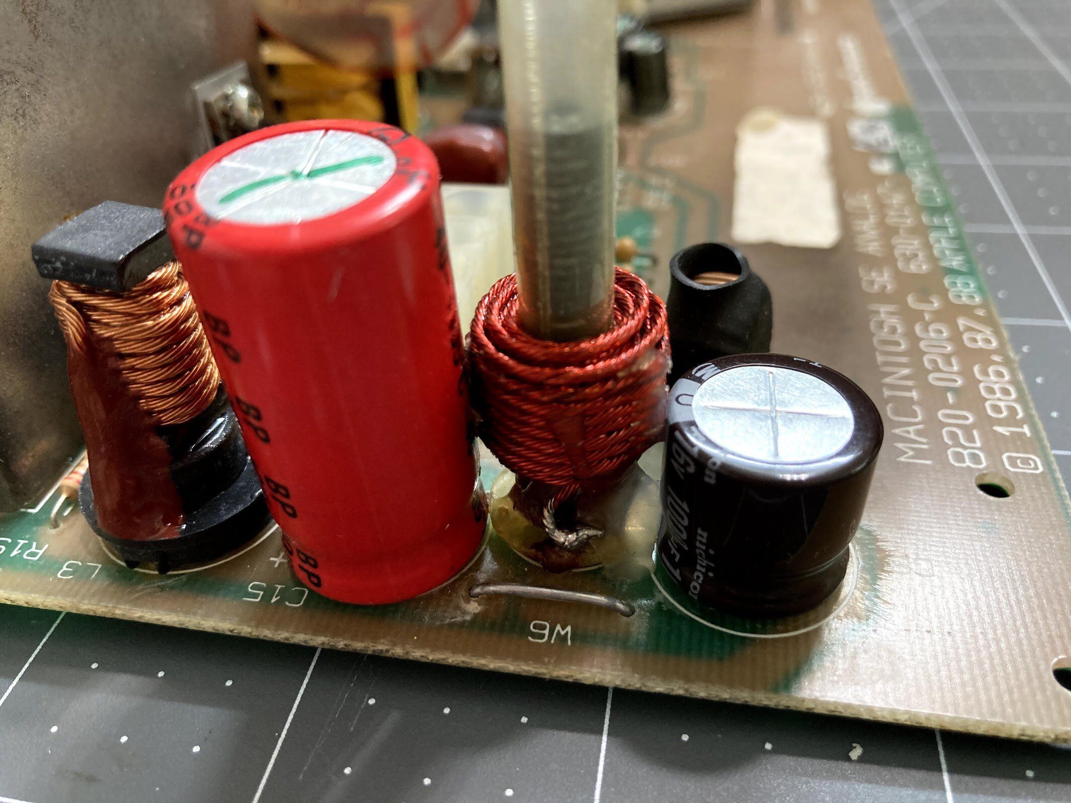
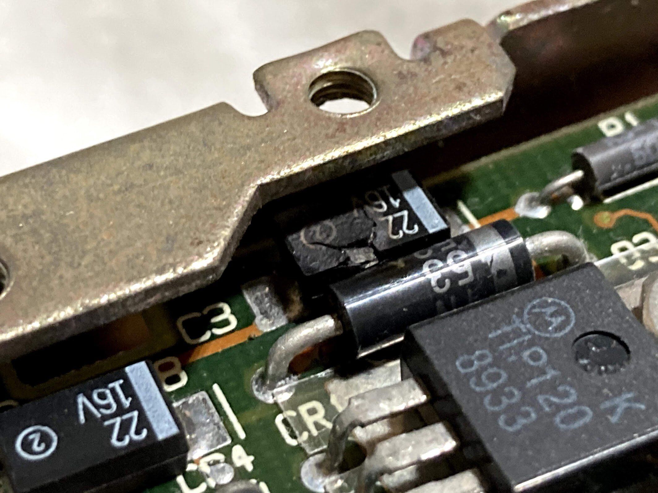
Analog Board Recap
Next, it was time to recap the analog board. I don’t always immediately jump to recapping the SE or SE/30 analog boards, but considering the mess that this machine was when I got it, I figure it could use all of the help it can get. Besides, maybe some fresh caps will help that dim CRT out?
Normally, I like to provide an exact capacitor list in these build threads. Unfortunately, I did this recap (and all of the restoration that you’ve read about so far) in the Spring of 2020 - right when COVID was hitting everything, and supply chains were a mess.
Because of that, I wasn’t able to replace every cap. Additionally, several of the caps that I used are now out of stock, or have become obsolete. In light of this, I’ve updated my list of Macintosh SE Analog board capacitors, but you’ll want to double-check my work and make sure it is complete. I know at least one cap (a non-polar one) is not on the list. Anyway, here’s a link to add my capacitor kit to your shopping cart on DigiKey.
Now, let’s get to the recap of the… uh… recap.
First, I marked the old caps with a green Sharpie to keep track of what I’d replaced.
Then, one at a time, I desoldered caps. Sometimes I heat one leg and rock the cap, sometimes I used the soldering sucker, and sometimes desoldering braid.
New cap installed here! I always solder one leg, and apply gentle pressure from the back while reheating that leg, which seats the cap firmly against the board.
Here’s a new cap, and an old cap that I couldn’t get a replacement part for. I try to find the same diameter and leg spacing, but I don’t worry about height. I also try to use Nichicon or Panasonic for electrolytic caps.
With that, the analog board is recapped!
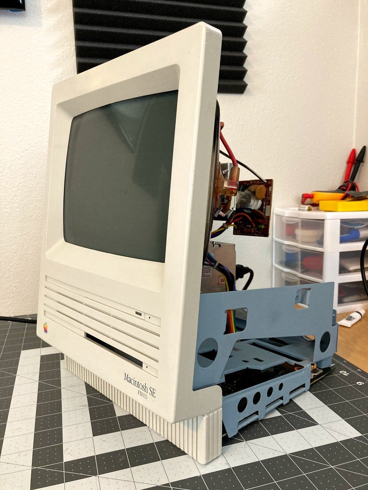
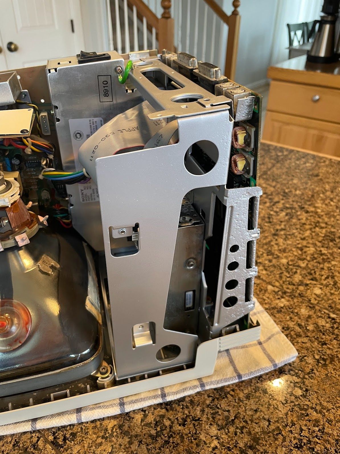
Reassembly
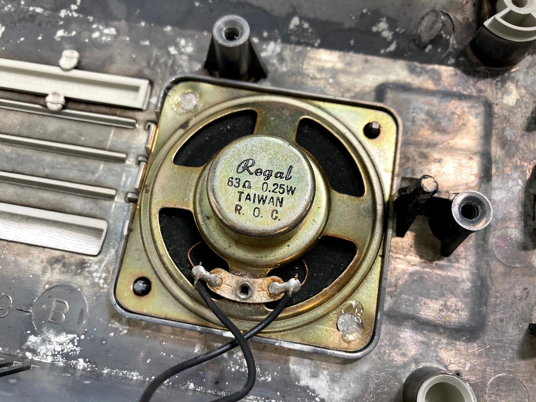
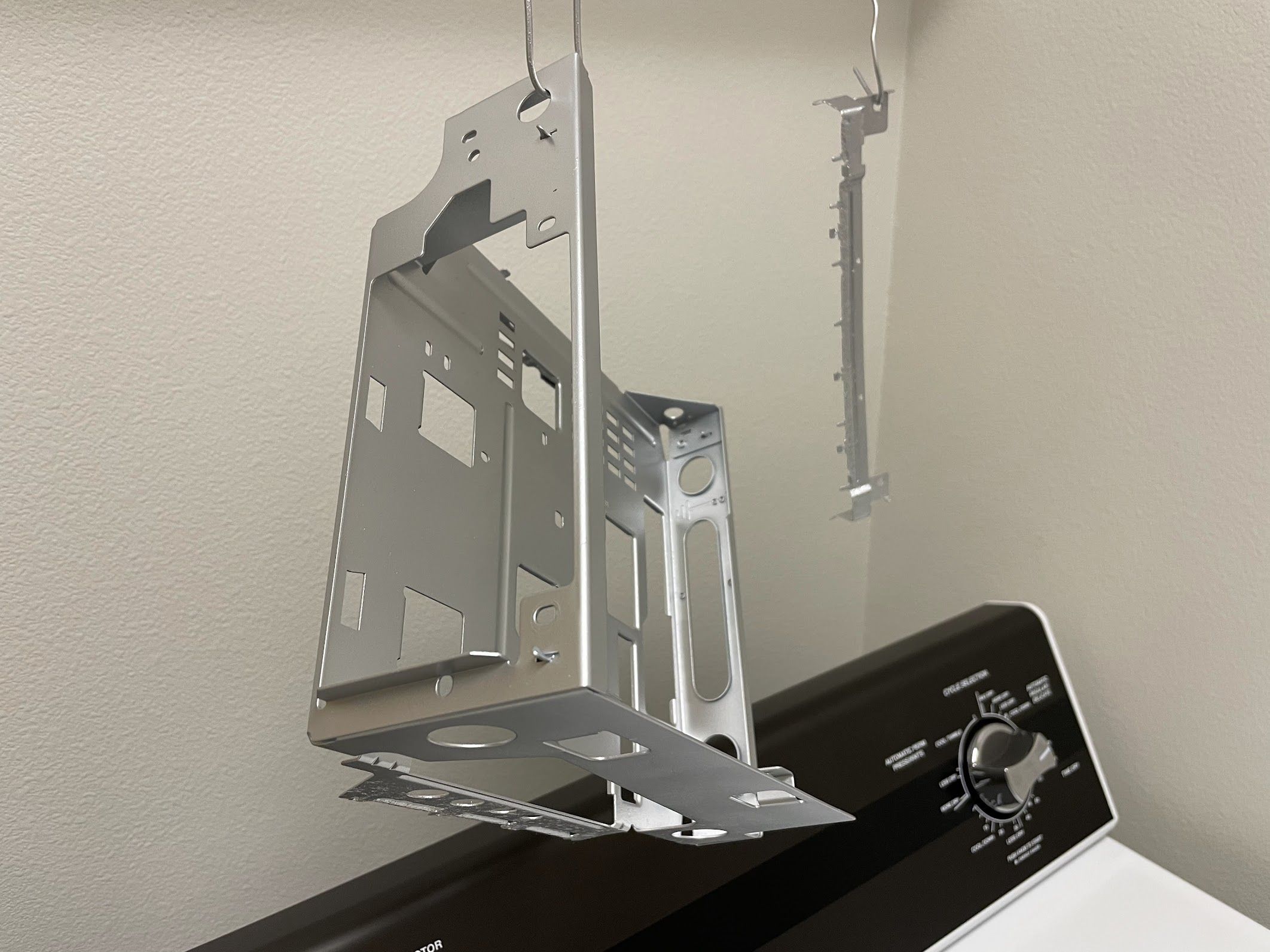
At last, time to reassemble! Good thing too… at the time, my office had two torn-apart SE’s, a torn-apart SE/30, and torn-apart external floppy drive! First, I hot glued the speaker back in. I find this method to be passable at best… sometimes, the speaker pops back out. I feel like epoxy would be a bit much, so I’ve just been using hot glue until I discover something better.
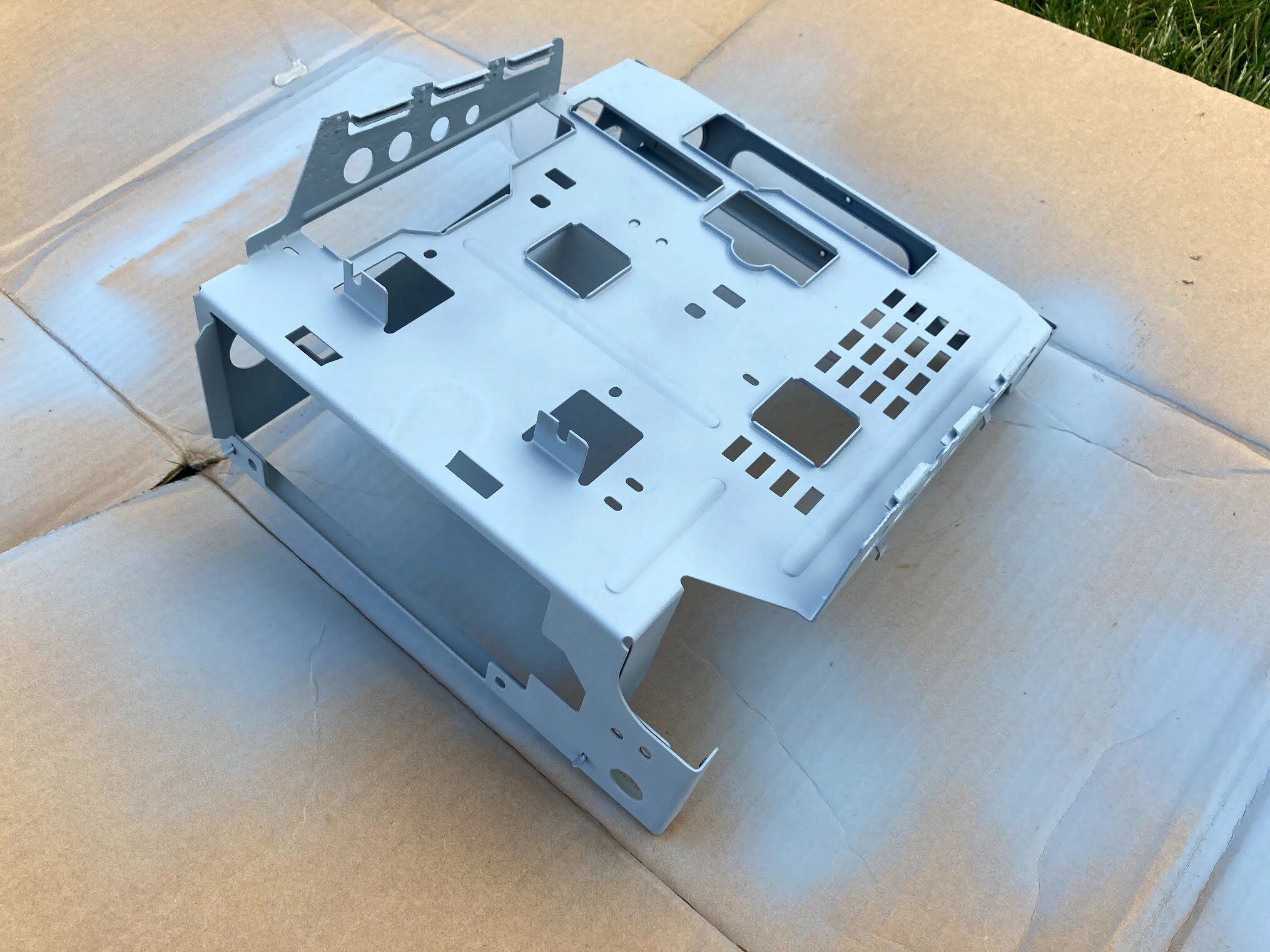
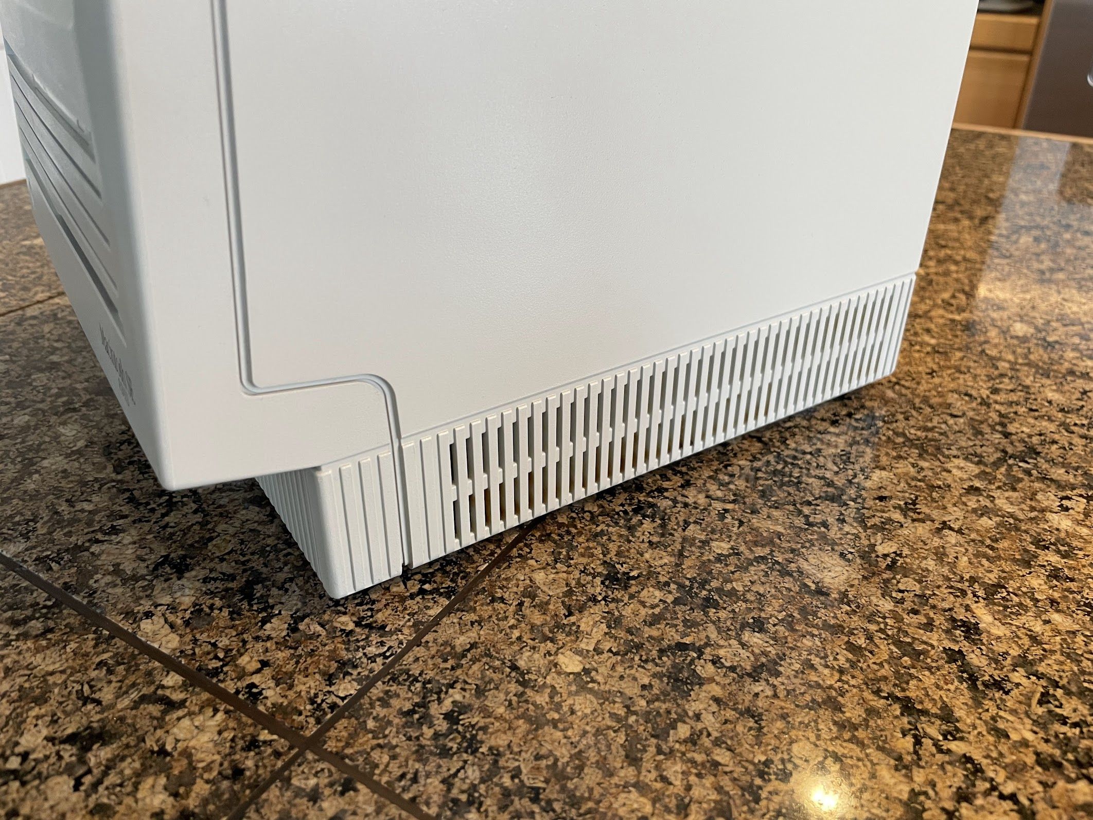
Next, I reinstalled the chassis. Yikes, it is blue! But at this point, I had decided that there was no need to spend money on grey or silver paint. I just wanted to stop the rust. I have plenty of Macs that I make “perfect”. Most people would have just thrown this one out anyway, I’ve already put too much effort into it. Right?
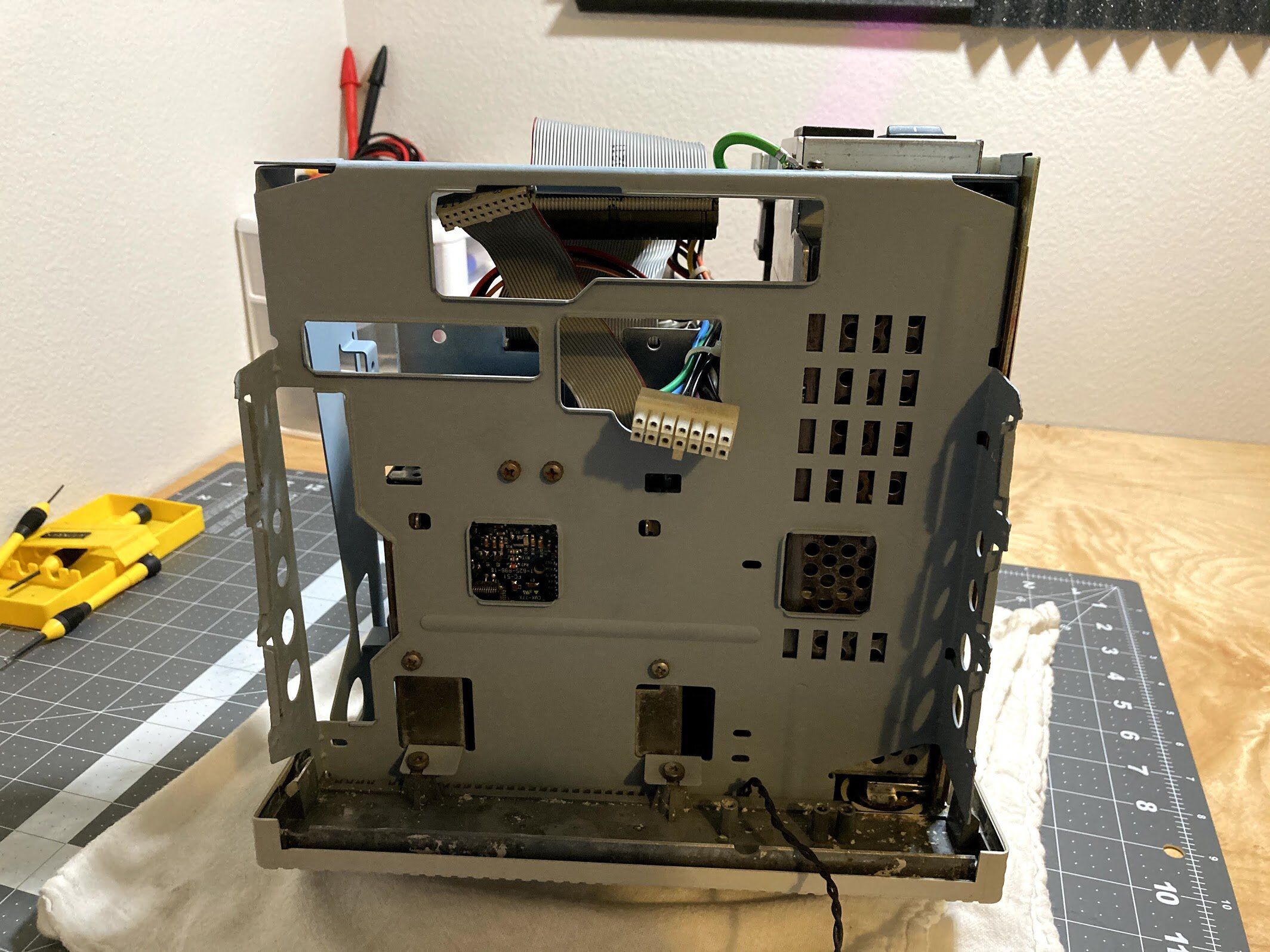
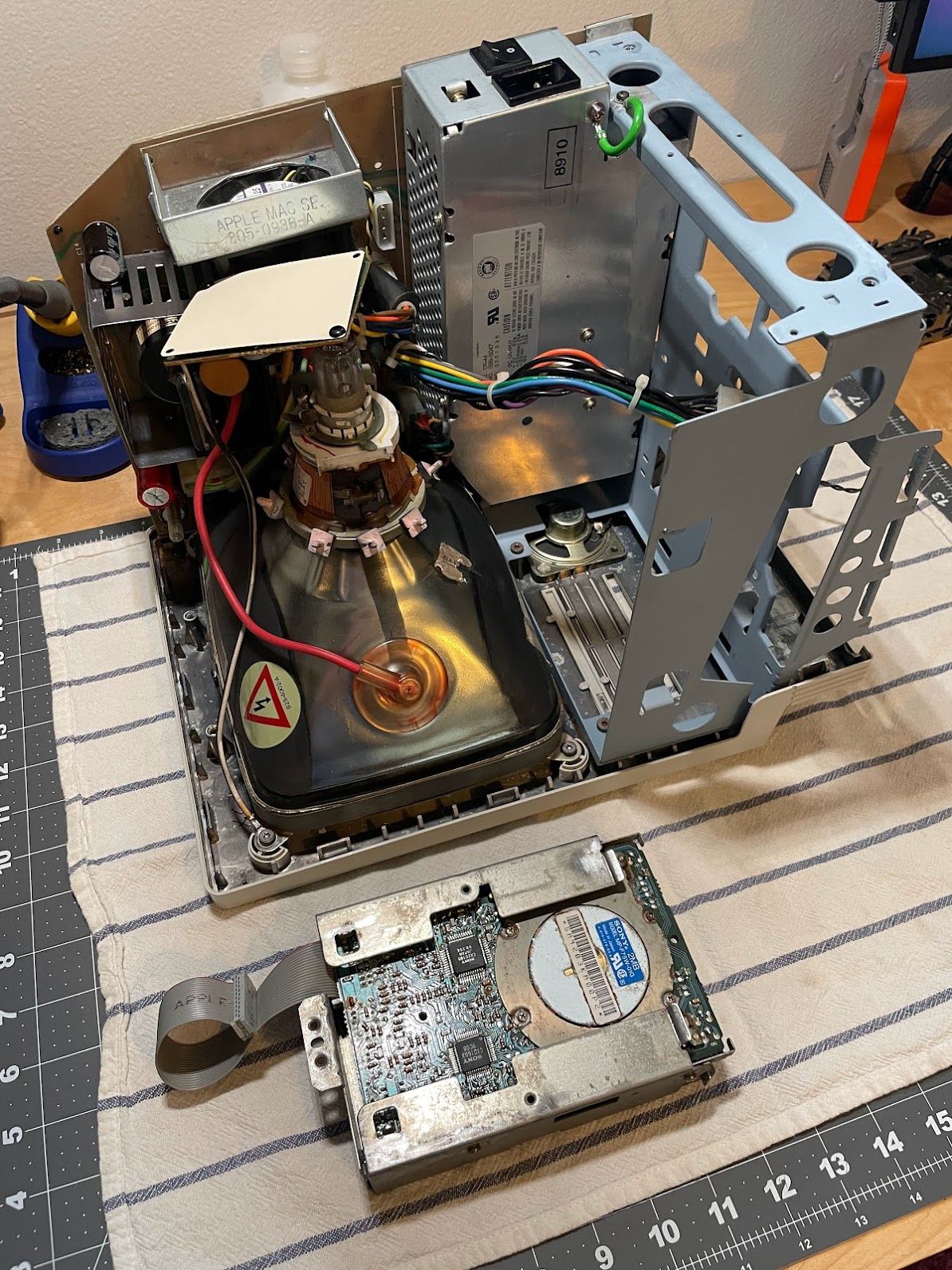
Jumping ahead a bit, I installed the analog board and logic board, but left the floppy drive and hard drive out to do a quick power-on test.

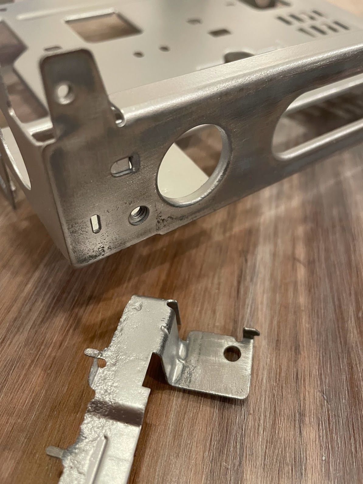
The ground lug on the CRT was a bit rusty, so I cleaned it up with some sandpaper to ensure a good connection here.
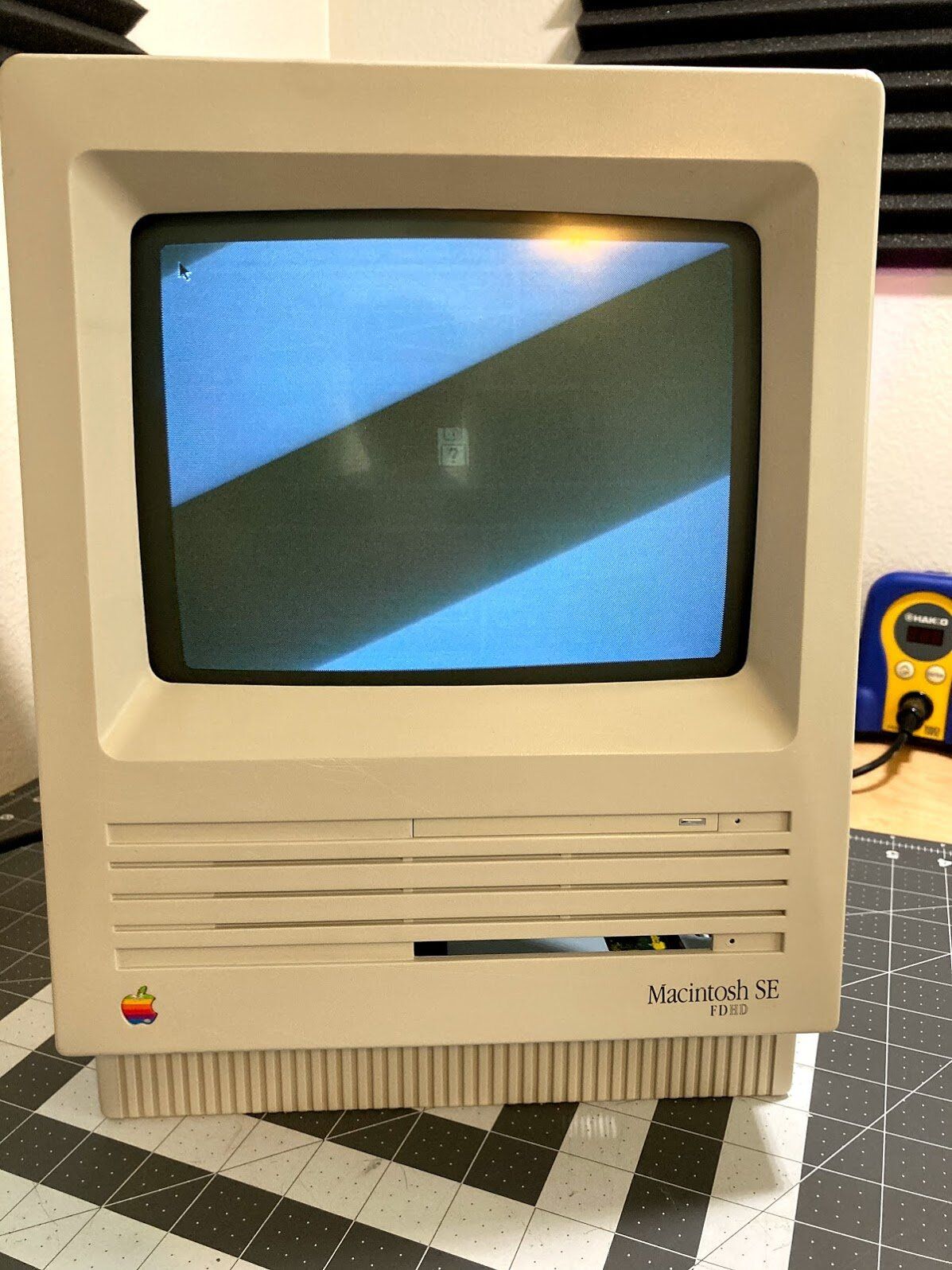
Time for the power-on test!
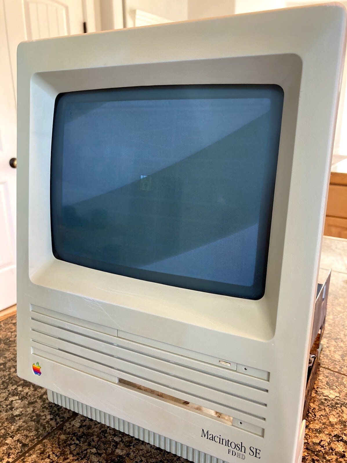
Yep, still works! One thing I hadn’t tested before now was sound. No problem, it chimed as usual. The CRT is pretty far out of adjustment. I’ll need to adjust rotation, width, height, and centering at some point.
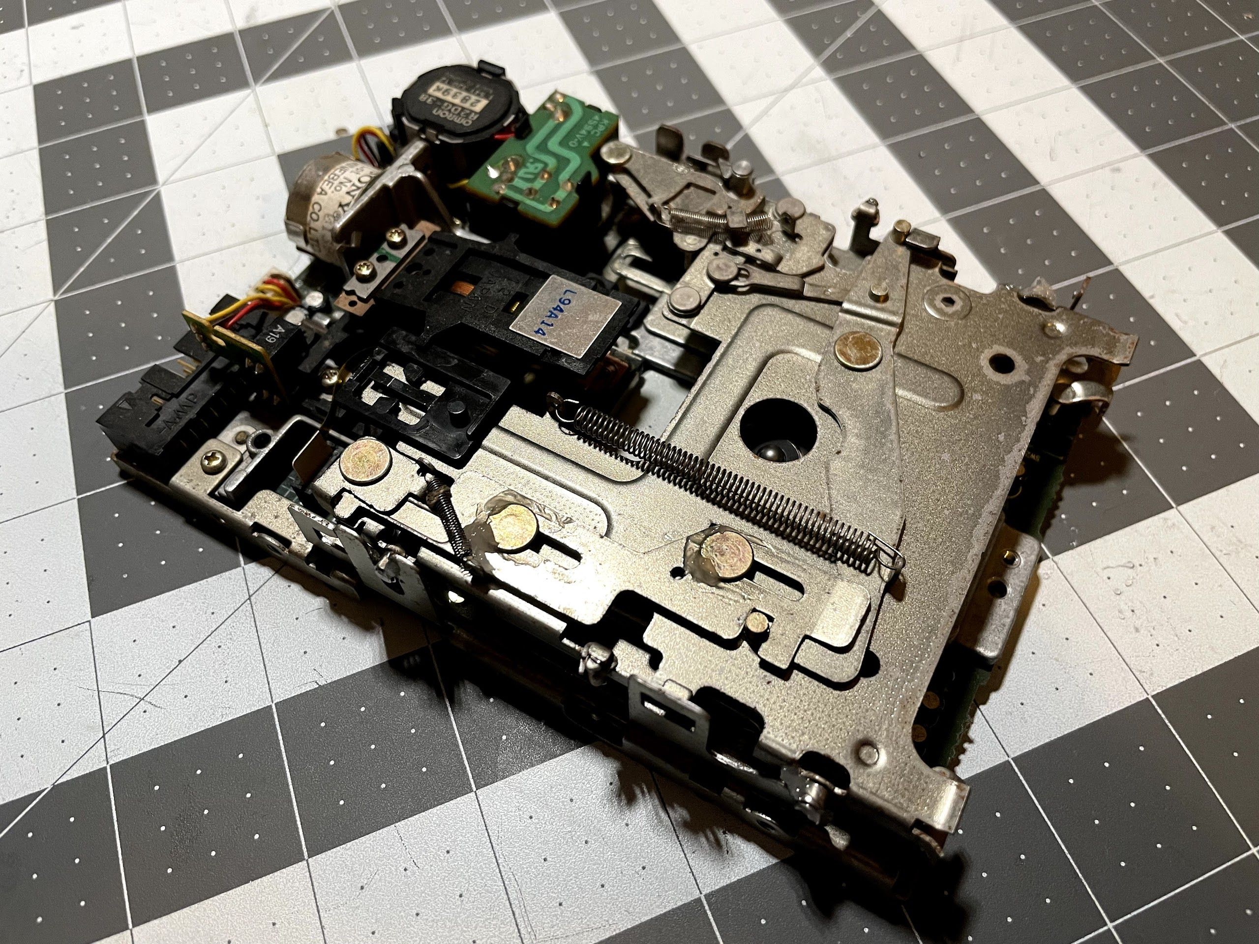
Floppy Drive
Next, it was time to service the floppy drive. Before tearing into it, I had pretty high hopes for it. Up until this point, I’d been able to resurrect every drive I’d come across.

I won’t waste your time on this one, though. After soaking rusted parts in vinegar, thoroughly cleaning everything, and lubricating all of the moving parts, I reinstalled the floppy drive and hard drive.
At this point, both the hard drive and floppy drive were completely untested. It was finally time for the big moment where I would see if the floppy drive worked, and if the hard drive worked, and if there was anything interesting on it!
I flipped on the power, and immediately, very bad things started happening. The machine rapidly went “FLUP FLUP FLUP FLUP FLUP”, and by the time I got my hand back around to the power switch, there was a big puff of magic smoke coming from the hard drive and floppy drive area! Oh no!
With the power back off, I waved all of the smoke away and took things back apart to find out what burned up. And burn up, something did! My office smelled horrible! I was really hoping that whatever had failed was the hard drive, and not the floppy drive or logic board. The logic board checked out okay, but I quickly discovered this on the hard drive:
Looks like a Tantalum capacitor gave up! If I had to guess, I’d say that the spindle or stepper motor was stuck, it overwhelmed the circuitry, and yet another MiniScribe died. Oh no! Anyway…
I was a bit worried that the hard drive might have damaged the machine, but that didn’t seem to be the case - it powered on and chimed just fine, sans hard drive.
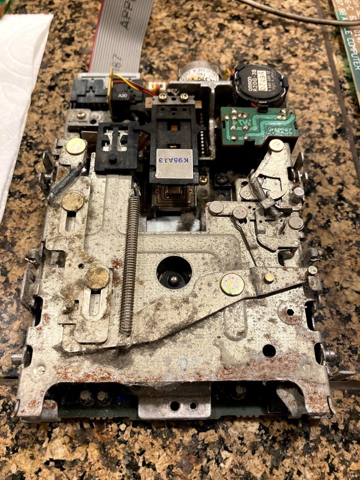
So, how about that floppy drive? Sadly, no luck here either. On power-on, something in the drive just buzzed and buzzed. I tore it back apart to find that the r/w head actuator motor was full of rust. Since it’s a sealed unit, there’s no possibility of repairing it. I’d have to either get a replacement motor, or replacement SuperDrive.
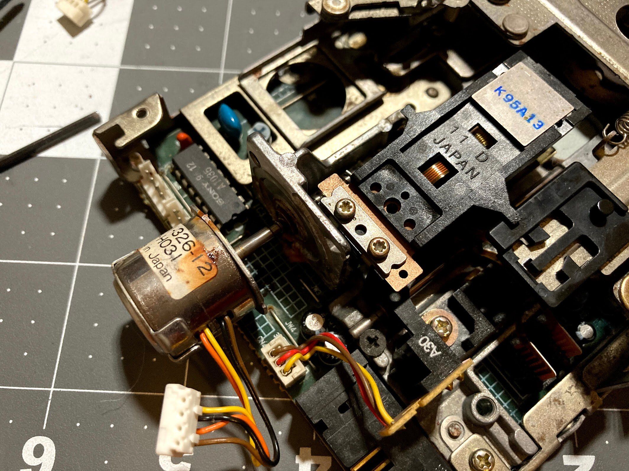
Fast forward about 11 months, and Eric (who leads the development of the excellent BlueSCSI project) sent me a donor SuperDrive for this machine. I specifically asked him to not service it, so we could go through the process here.
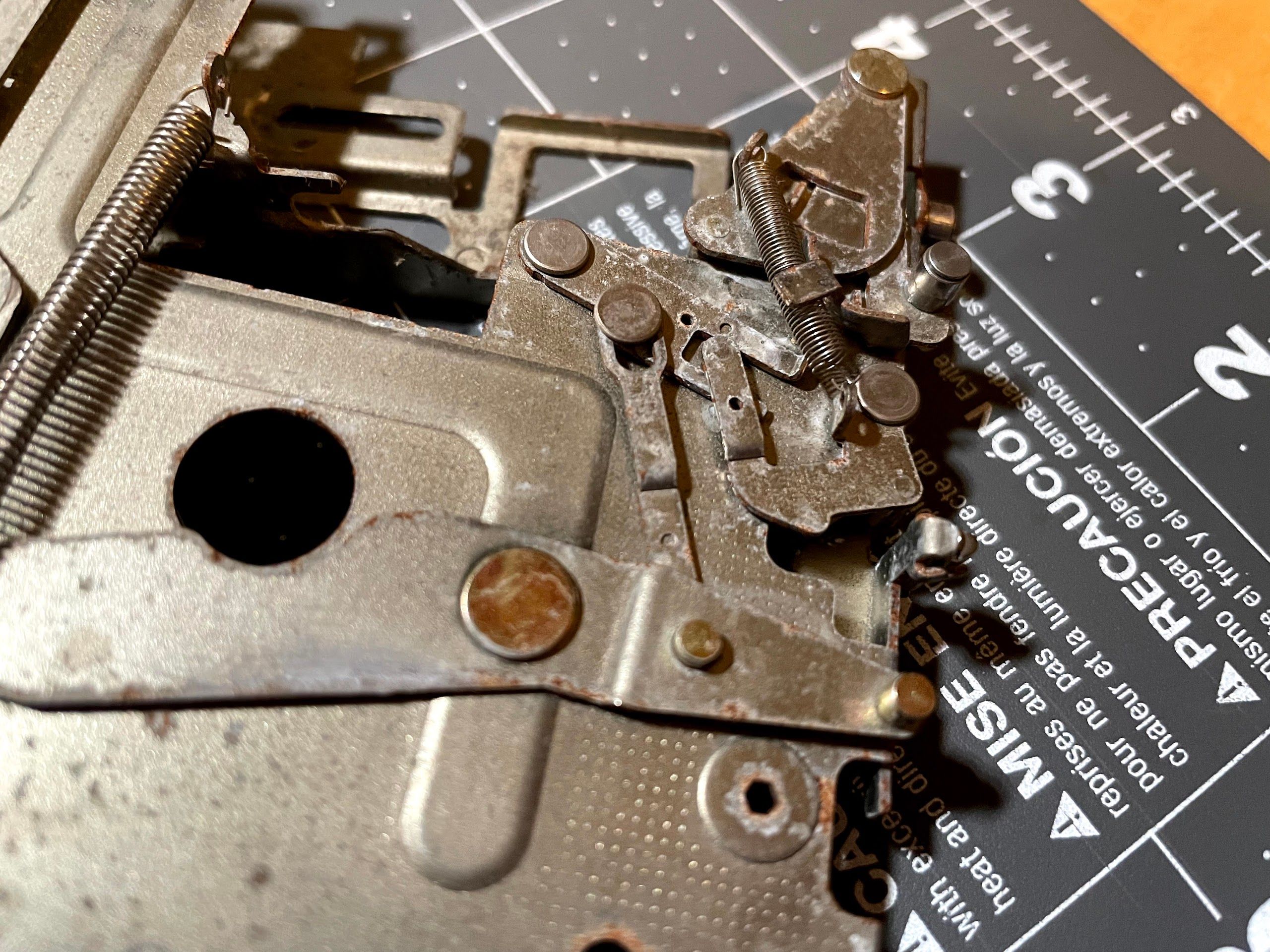
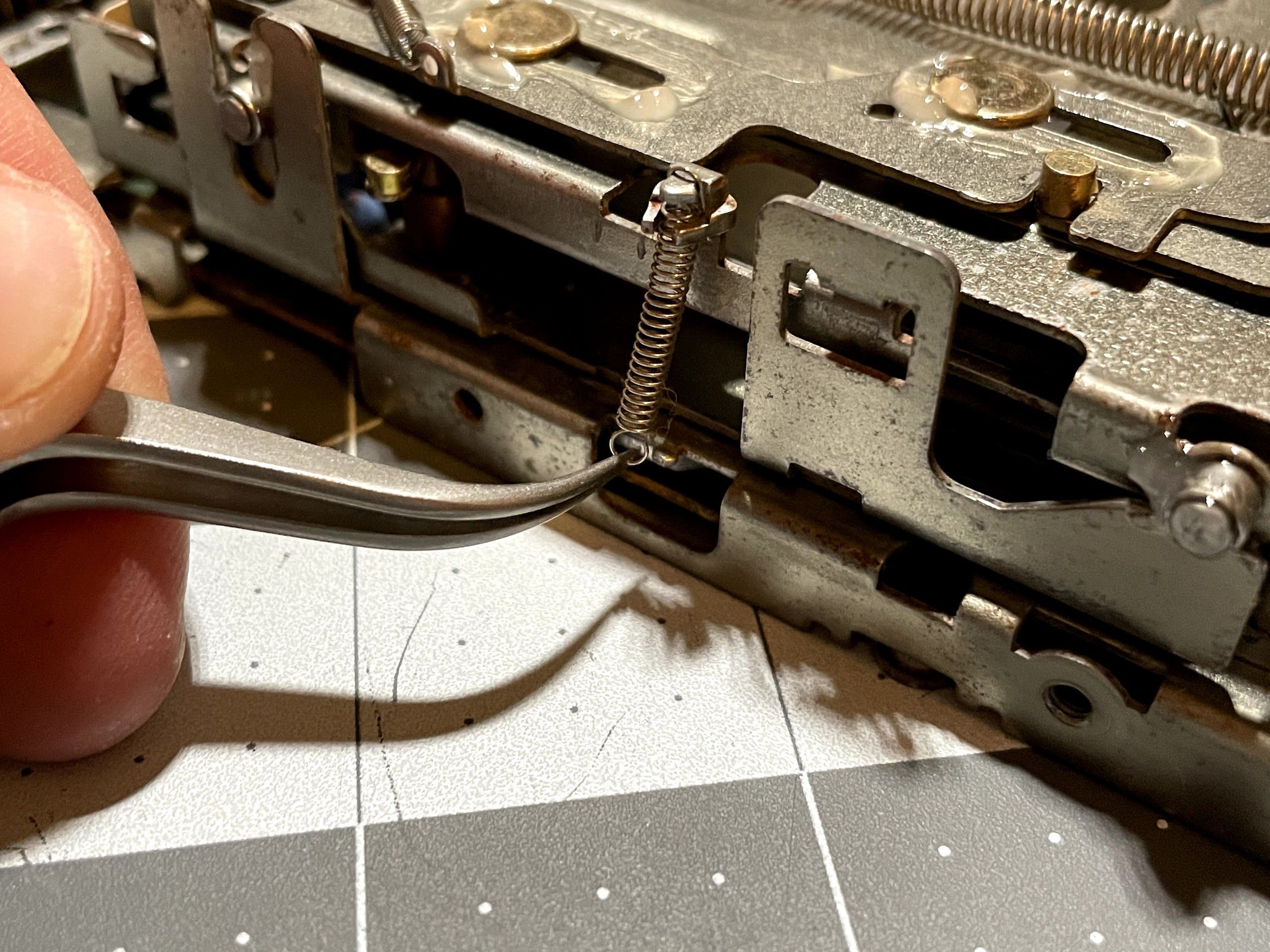
First, I used tweezers to disconnect the springs. They stay attached on the top.
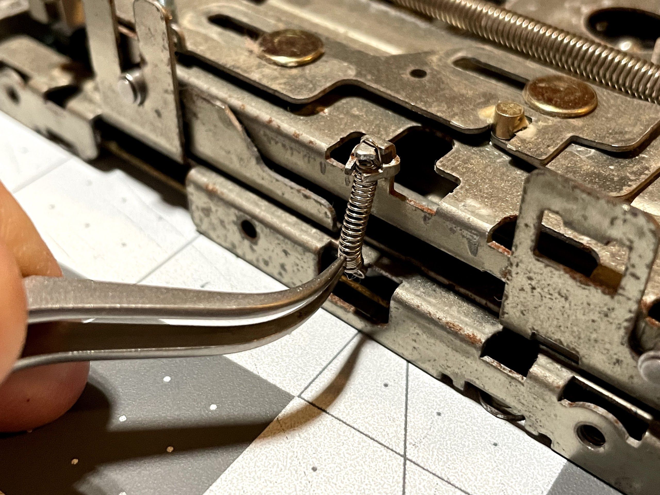
Next, I removed the two screws that hold the eject motor into place. I recommend being careful with these - it’s easy to strip the heads!
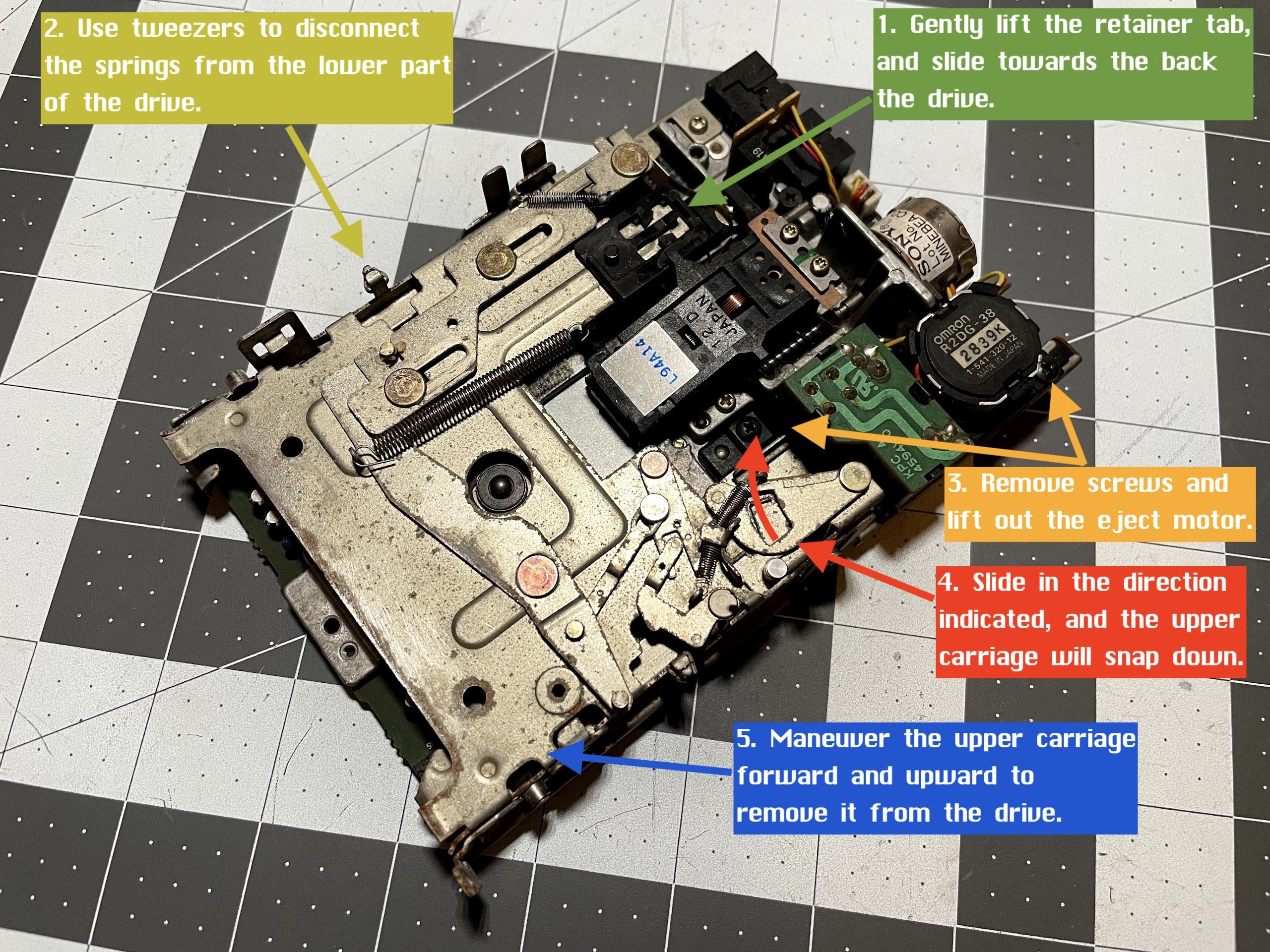
The next part of kinda hard to explain, so I made a quick diagram showing all of the steps. Step 4 is a bit tricky - I always forget exactly how to do it, but you’ll know the instant you figure it out as the drive snaps into position. Step 5 involves some maneuvering, but you can work the upper carriage out pretty easily.
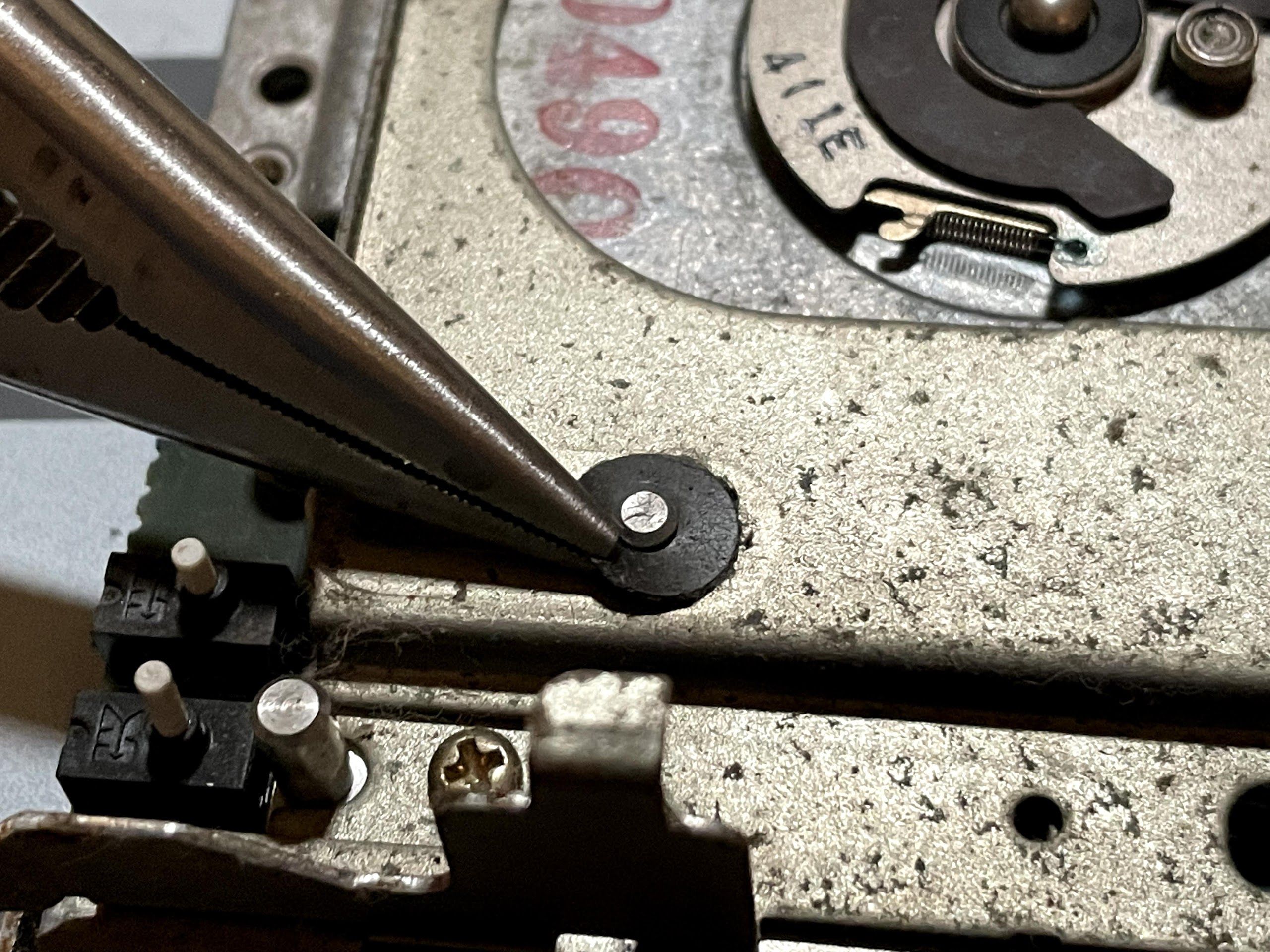
After removing the upper carriage, use pliers to remove the little snap-rings that hold the lower carriage to the drive.
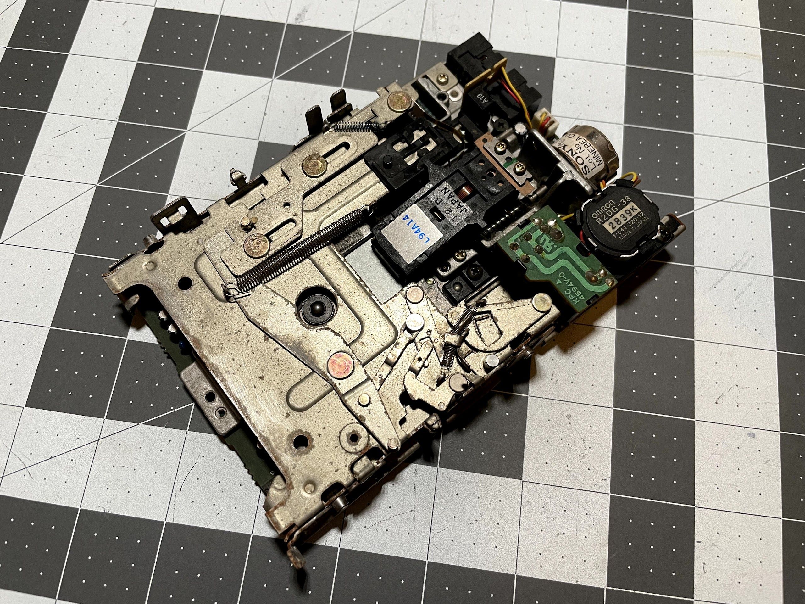
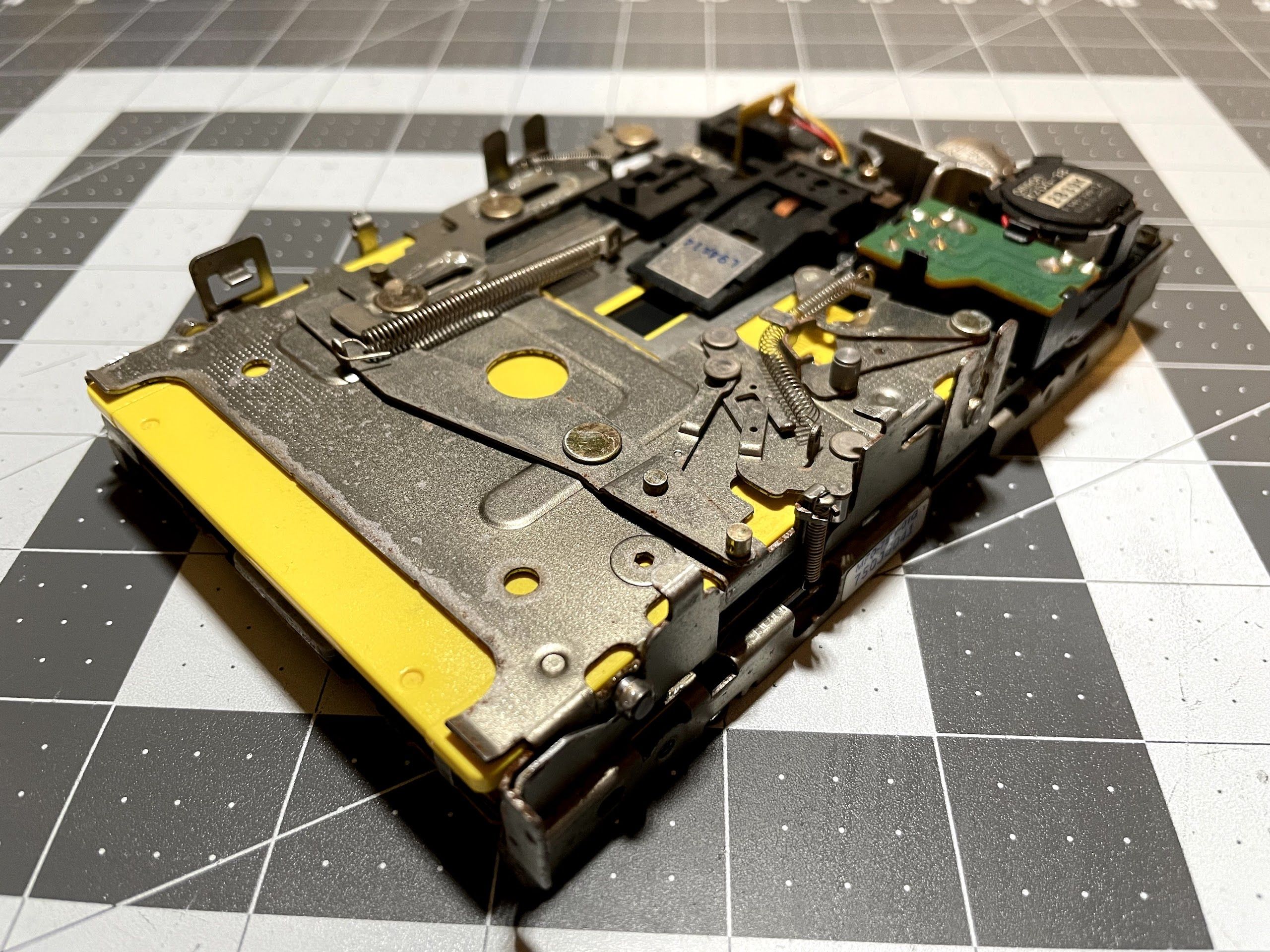
With that, the drive was completely disassembled.
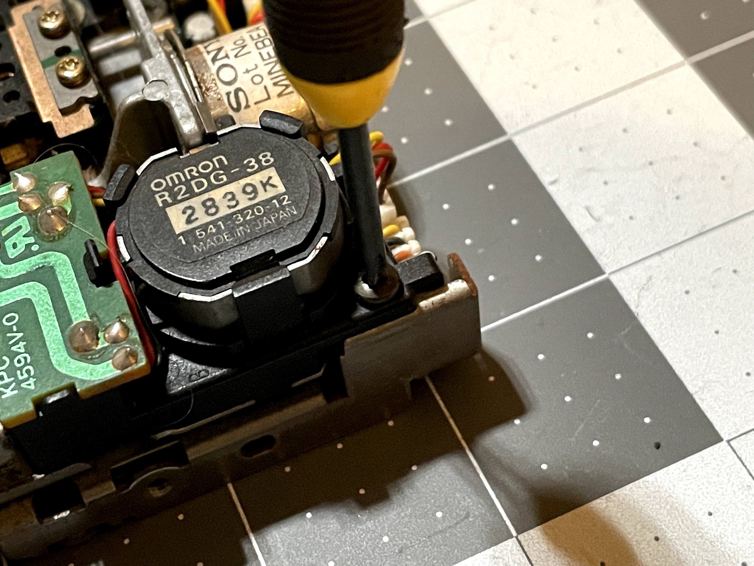
Next, I decided to clean up and lubricate the eject motor gears. I used a small screwdriver to pop the metal shield off, exposing the gears.
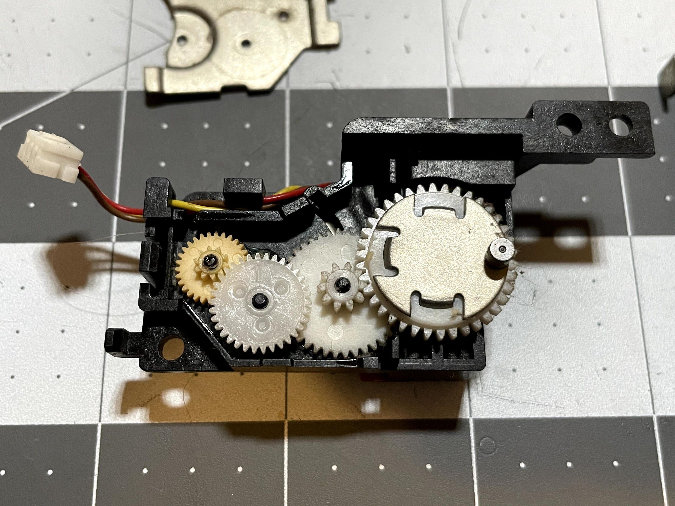
A couple of the gears can be removed easily with tweezers. The dark yellow one is know to break, but fortunately, there are 3D printed reproductions available. These prints are done on a different type of printer than my FDM (fused deposition modeling) printer that can hit much higher resolution. Fortunately, we don’t need a replacement gear here yet. I always clean and lubricate these drives before using them to try to avoid snapping a gear.
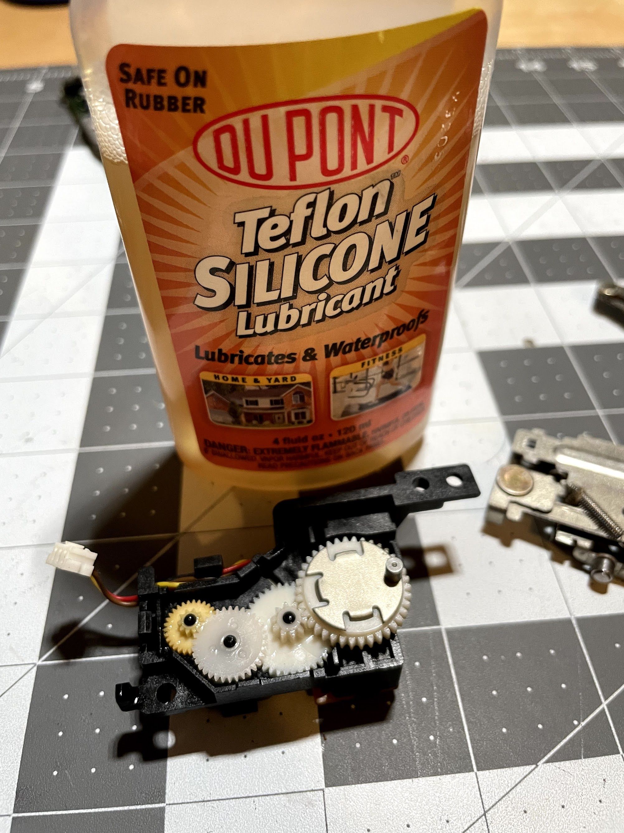
I swabbed everything out with alcohol and cotton swabs, then added a couple of drops of Teflon Silicon lubricant.
With the eject motor reassembled, I turned my attention to the upper and lower carriages.
To deal with the rust and corrosion, I scrubbed them down in some vinegar.
After the vinegar, I used dishwasher soap and water, and then dried everything off with the air compressor. Not perfect, but a lot better!
I didn’t get any photos of this, but I hit the drive with the air compressor, swabbed the heads with alcohol, and use alcohol and cotton swabs to clean up the linear rail and leadscrew. I dabbed some grease onto them, and it was time to reassemble!
First, I greased the little bumps on the bottom of the lower carriage.
I reinstalled the snap rings by pressing them into place. They take a pretty good push! I usually use the soft, squishy part of my thumb.
I maneuvered the upper carriage back into place, and greased up a few of the moving parts. I don’t go crazy with grease… just a bit here and there.
I reattached the springs.
After reinstalling the eject motor, I tested it with a dead floppy disk. At this point, the drive was ready for reinstallation in the Mac!
Fast forward another 6 months, and I was ready to push through and get this restoration done, as it had been ongoing for about 1.5 years at this point. The next step was to focus on a hard disk replacement.
Not only did we lose a Tantalum capacitor on the original MiniScribe drive, but my SE/30 needed a hard drive bracket. To remedy these issues, I decided to build and install BlueSCSI.
BlueSCSI
I absolutely love these little things, because for about $25 and a MicroSD card, you can have solid-state storage in your retro Mac. There are so many things about this hobby that have become expensive. For storage replacement, that is no longer the case. Buying one is easy - just head over to scsi.blue!
Note: In the original post from November 2021, I assembled a BlueSCSI v1.0c. In 2025, we are well into the lifecycle of the BlueSCSI v2, which has a lot more capabilities (such as Wi-Fi), and is easy to source.
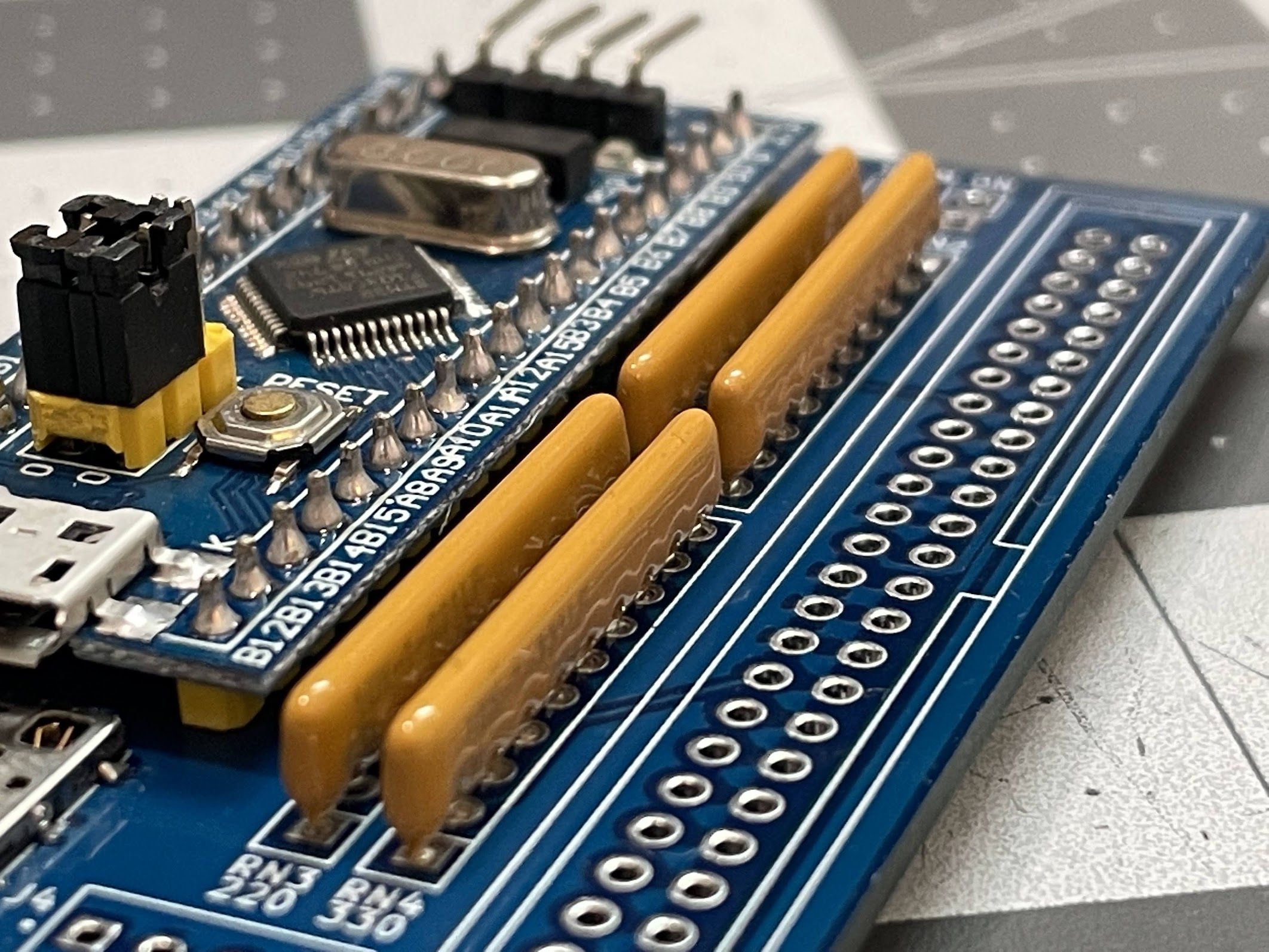
Before we can install it, we need to assemble it.
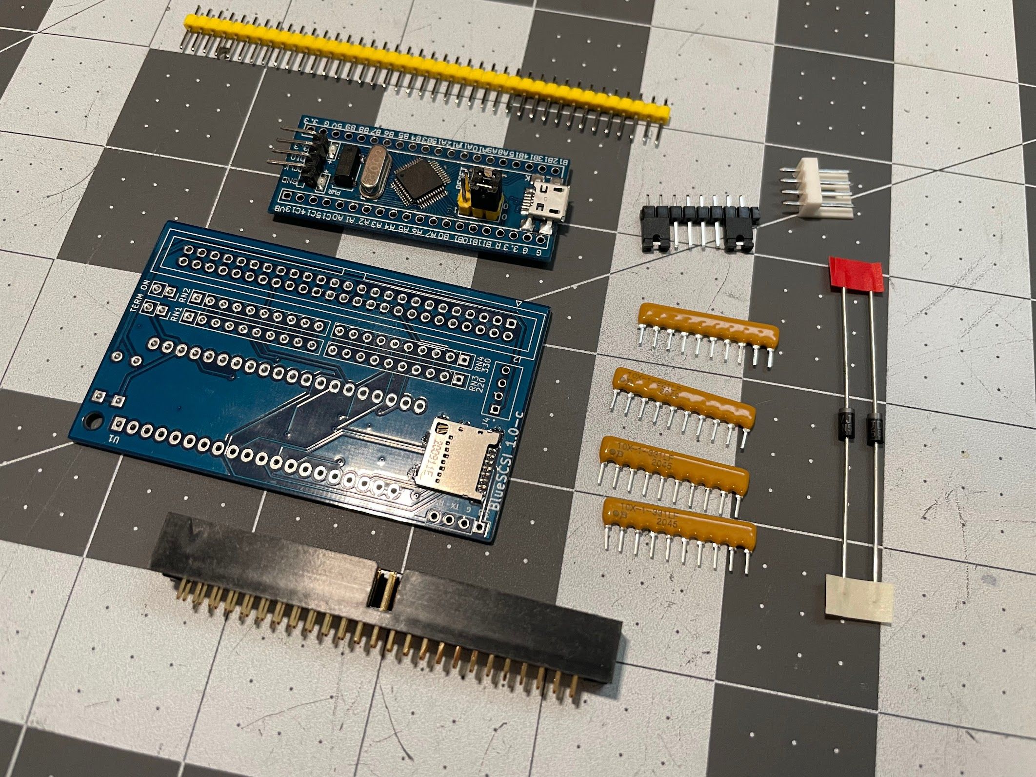
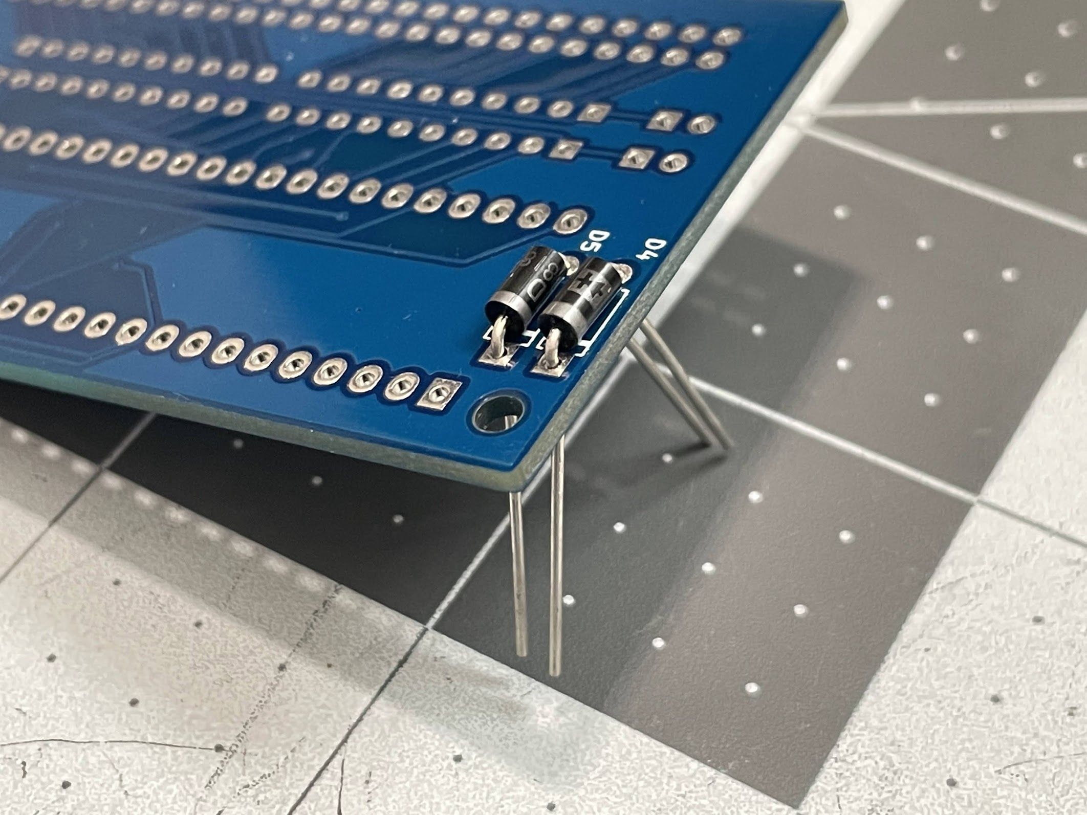
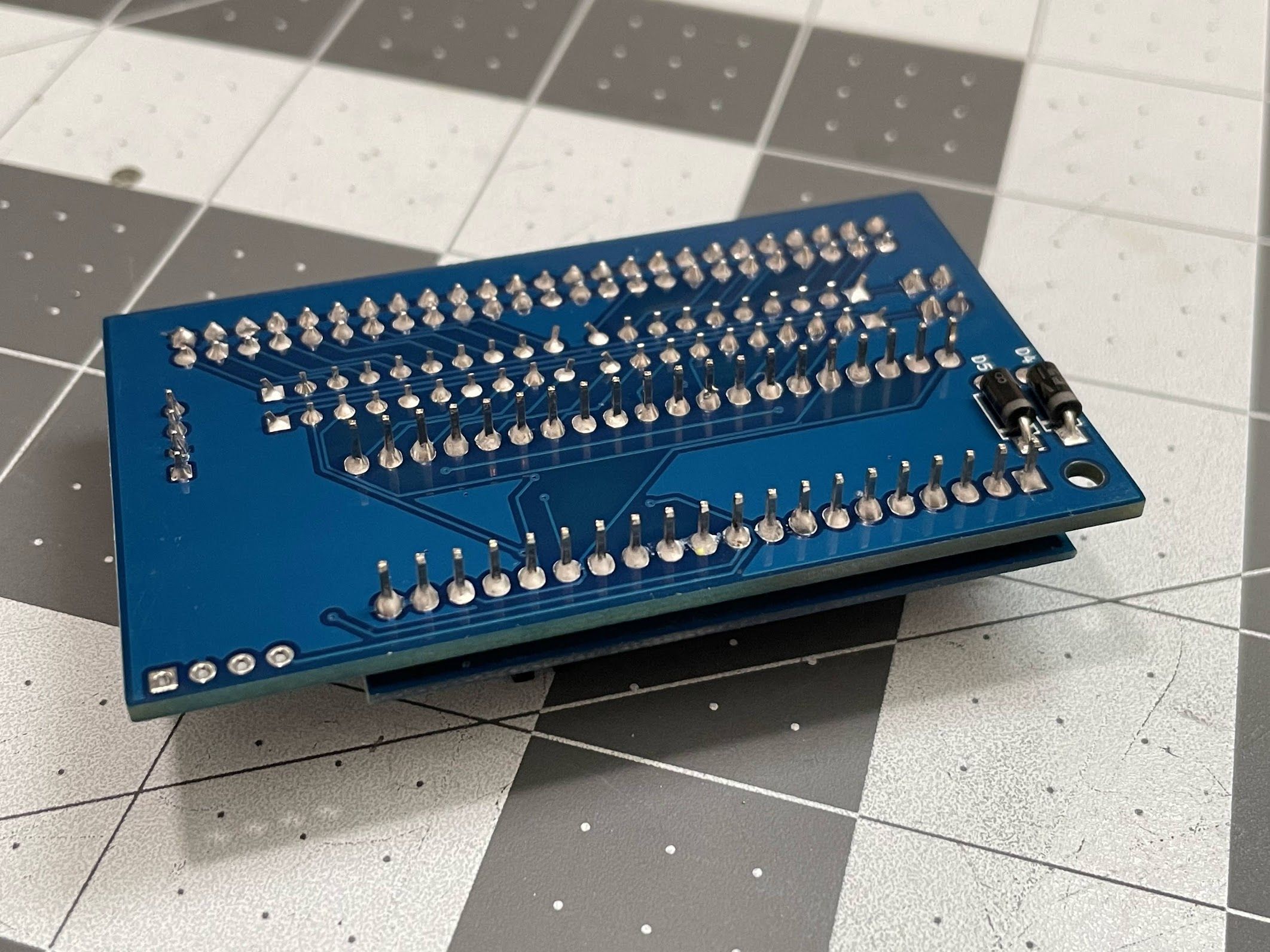
Following the BlueSCSI assembly guide, I solder in the diodes, which go on the bottom. They hold themselves to the board very securely.
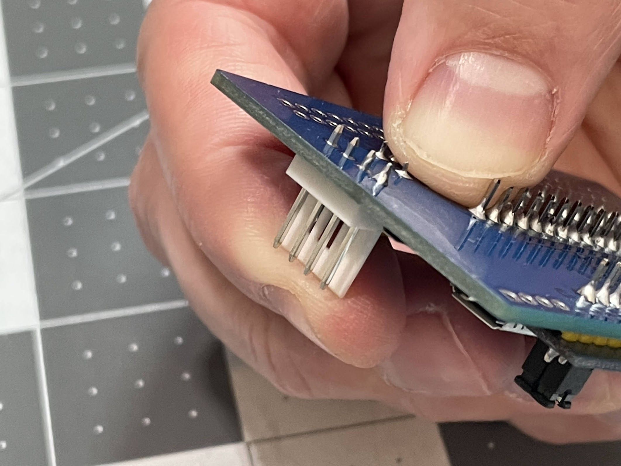
Next, I solder the pin headers to the BluePill. My favorite way to do these is with a breadboard, which holes everything nice and straight for soldering.
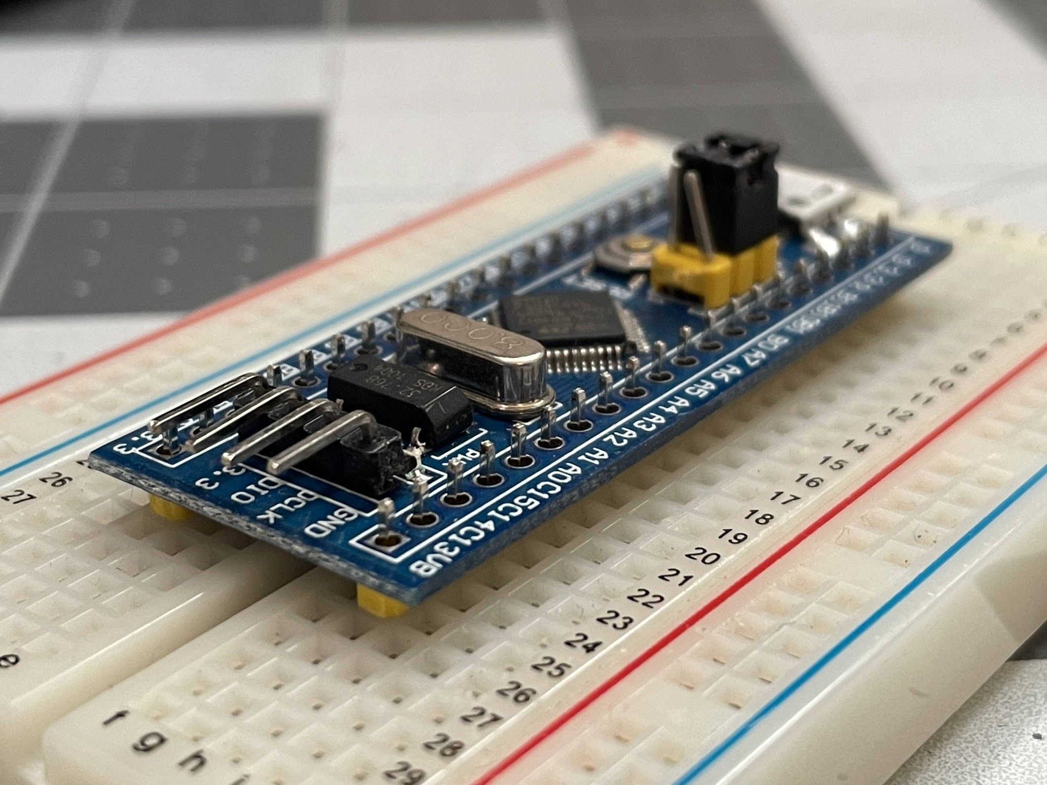
All soldered, and perfectly straight!
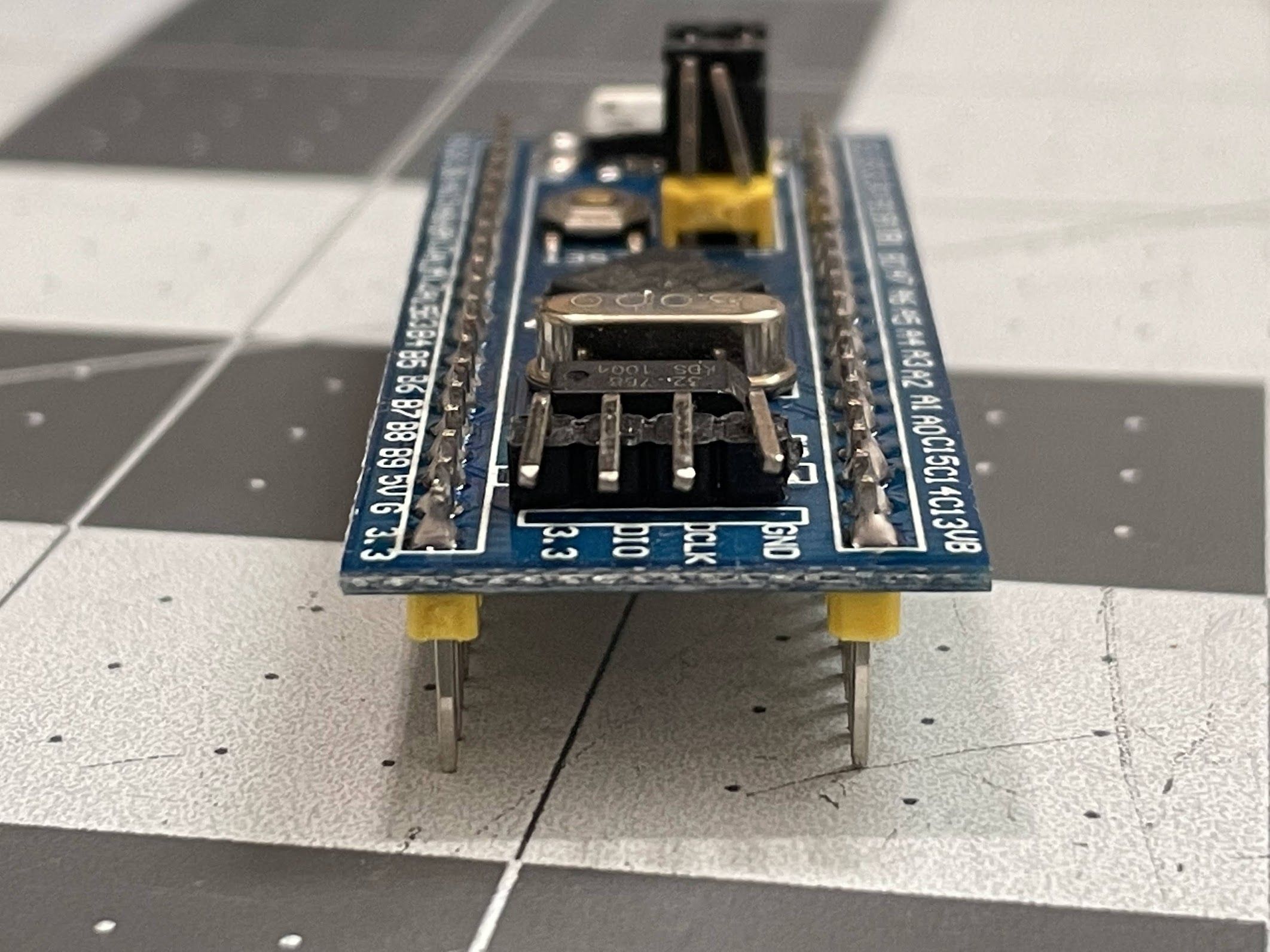
Next, I installed the BluePill onto the BlueSCSI board. Making sure the board is oriented correctly is SUPER important here - if you get it backwards, it’s a huge pain to desolder and flip around. Don’t ask me how I know!
Also note that I don’t cut the header pins off after soldering. You’ll see why in awhile.
Next, it’s time to install the resistor packs. I always use tweezers to bend the end legs outward slightly to hold it in place for soldering.
Here are the resistor packs, all soldered in!
Next, the Molex header for power. I don’t need it on this machine, but I like to solder it in for completeness. Getting this one in alone takes a bit of a trick:
Bend your solder up in such a way that you can “scoop up some solder” with your iron with only one hand. Fortunately, solder can be formed how you want it, and will do a good job of standing up on it’s own.
With your non-dominant hand, use your index finger to hold the header in place. Note that I’m holding it in by the plastic so I don’t get burned.
With your dominant hand, grab your iron, clean it, “scoop up” a generous amount of solder, and touch it to the pad and part for awhile. It will leave a nasty, poorly-flowed joint in place. Before you remove the iron, use your finger to get that header nice and straight. Remove the heat, hold the header still until the solder cools, and the part will now be tacked into place (which you can see in the photo).
You can now use two hands to solder the opposite pin.
Solder the two middle pins, and then reflow the first pin that you did.
I employ the same technique on the termination headers. Hold the part with one hand, use the other to tack it in…
…and then go back and “do it right”.
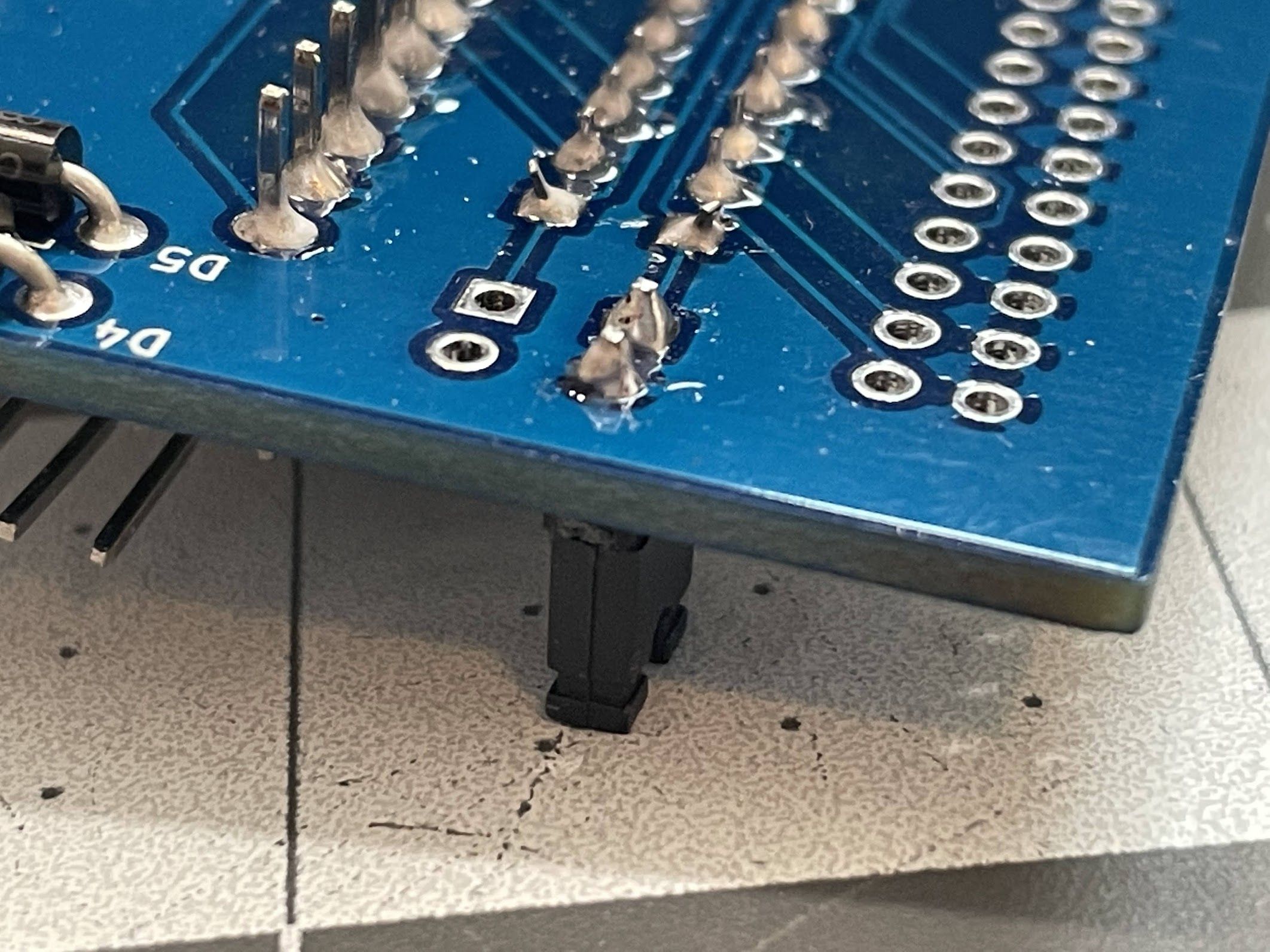
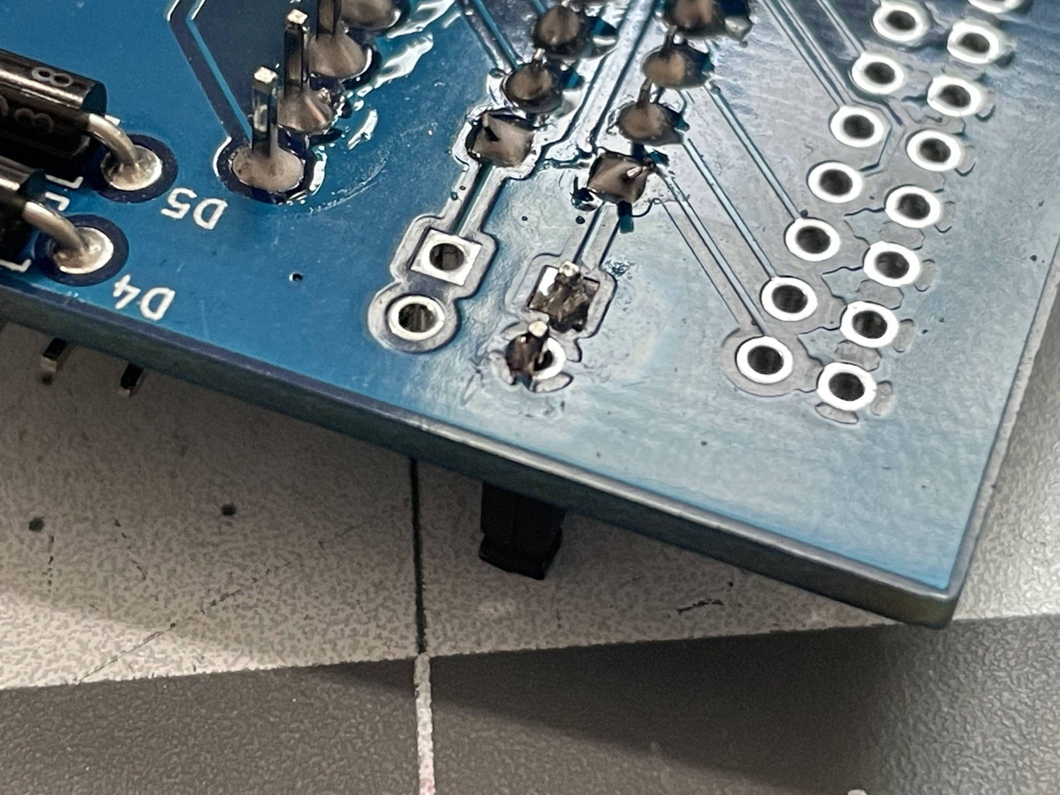
Finally, we can solder in the SCSI connector. I have a trick for these too:
Pick a pin in a corner, and solder it into place.
Push the header towards the board, and reheat the joint. The header will settle against the board.
Do the same thing on the opposite corner.
Your header is now perfectly flush with the board, and you can solder the rest of the pins.
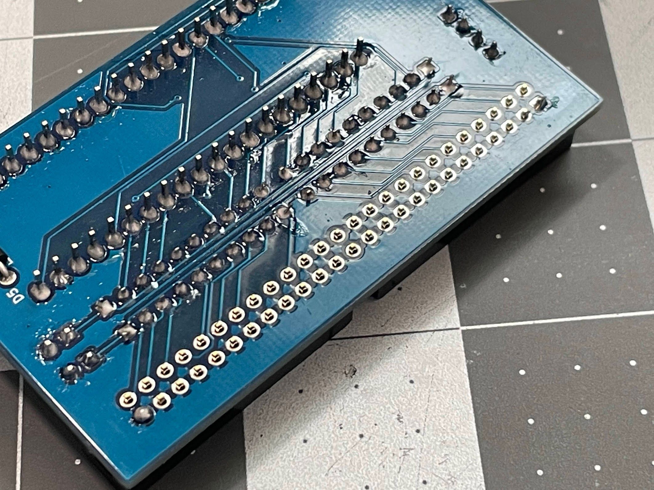
Next, I scrubbed the bottom of the board with Dawn and water, and hit it with the air compressor. It looks so nice and clean!
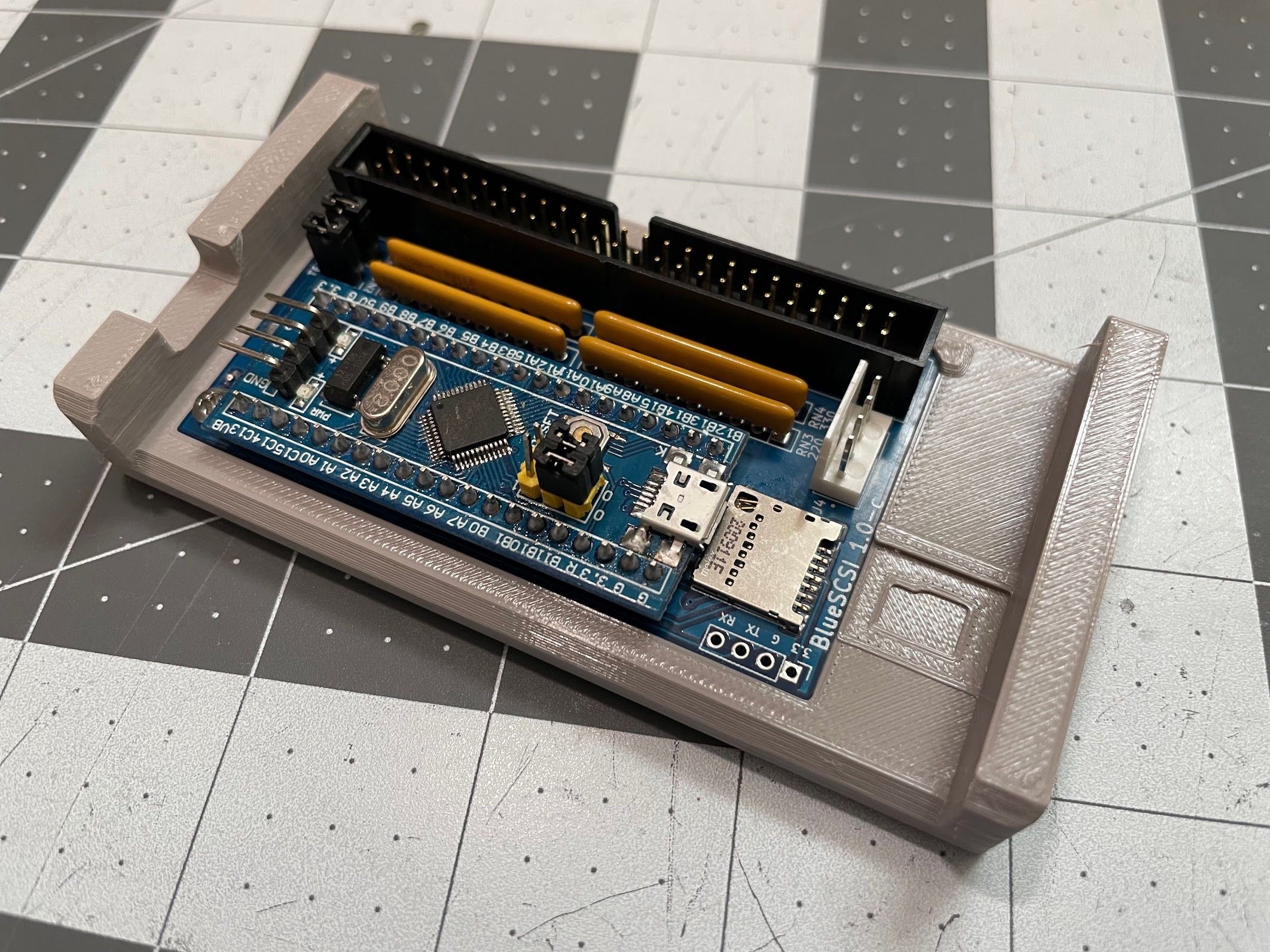
Finally, I installed the BlueSCSI into one of my printed brackets. If you’d like, you can get the files to print your own. The BlueSCSI hooks under the tabs on the front, and snaps down flush with the bracket.
There was one last thing to do, which was set up the MicroSD card. First, I formatted my 8 GB card as ExFat using Disk Utility on macOS 11.6 Big Sur.
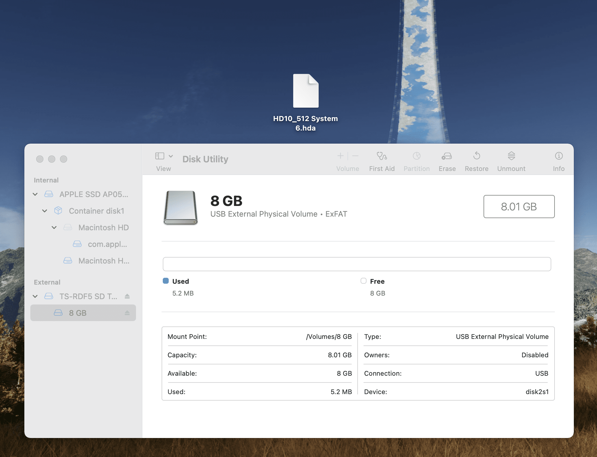
Next, I grabbed a RaSCSI System 6.0.8 Boot image from Macintosh Garden. These are intended for use with the RaSCSI, but they work on the BlueSCSI and are so, SO convenient. I unzipped the image, and renamed it to HD10_512 System 6.hda. If everything works right, this system will boot to a working copy of System 6.0.8, which is super convenient! From a software perspective, the BlueSCSI is insanely easy to use - I love it.

Chassis Painting
Ok, just a couple things left on this Mac! It’s coming together! It’s almost done!
No, no. I can’t leave it. It can be so, so much better. Time to take it back apart. Again.

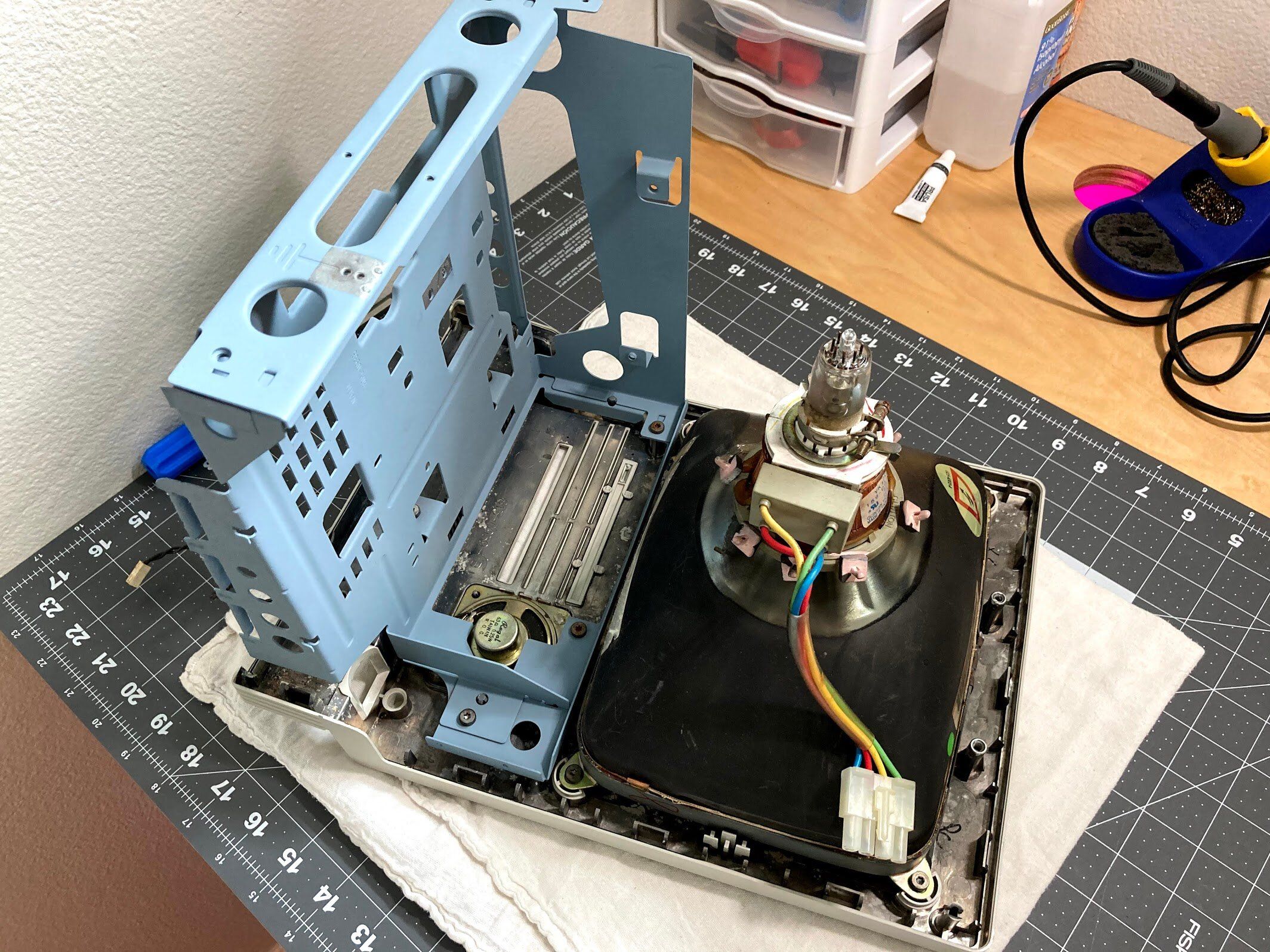
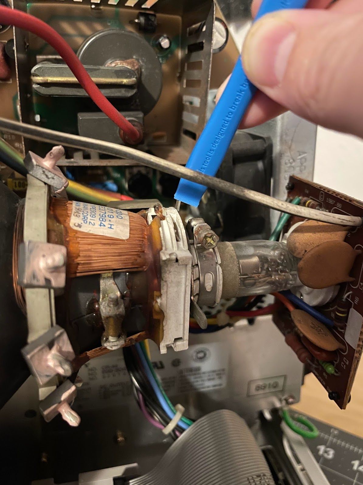
I may be anxious to get it fixed up, and while the SE does have a bleeder resistor for the CRT… safety first. I always discharge the CRT before touching the anode cap, anode wire, and flyback.
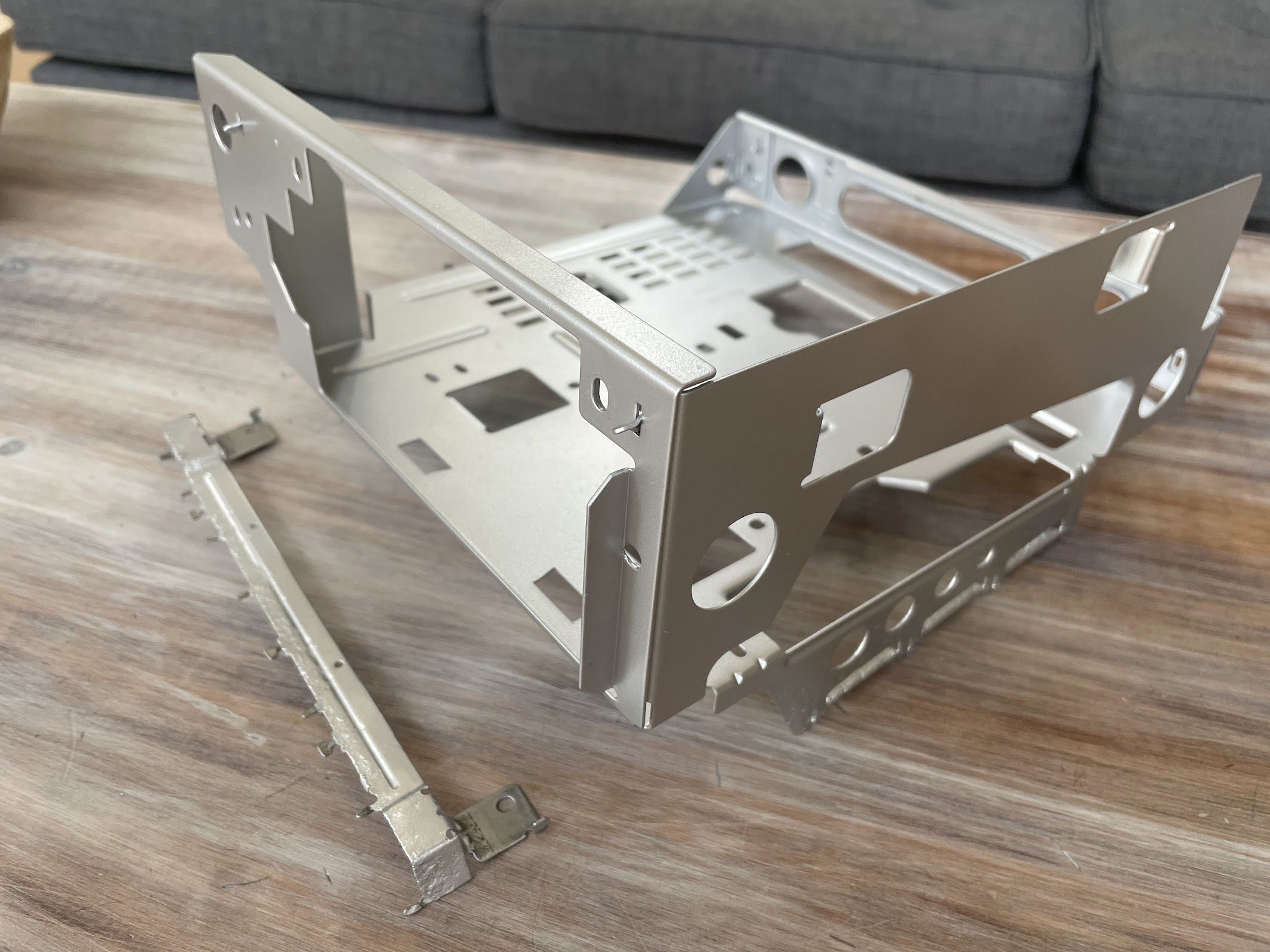
Here it is all taken apart, littering the floor of my office. Again. I didn’t even bother to disconnect the ground wire!
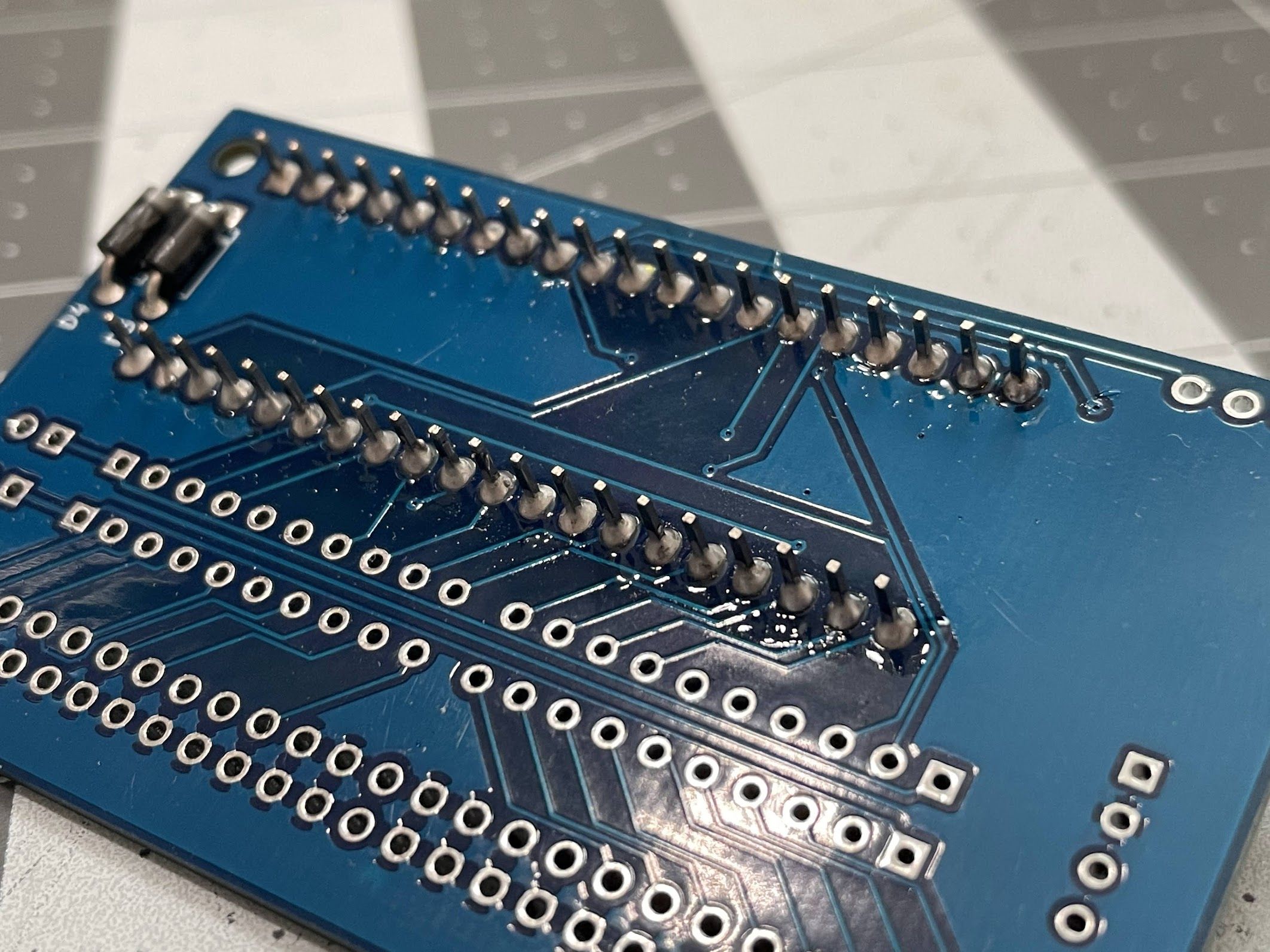
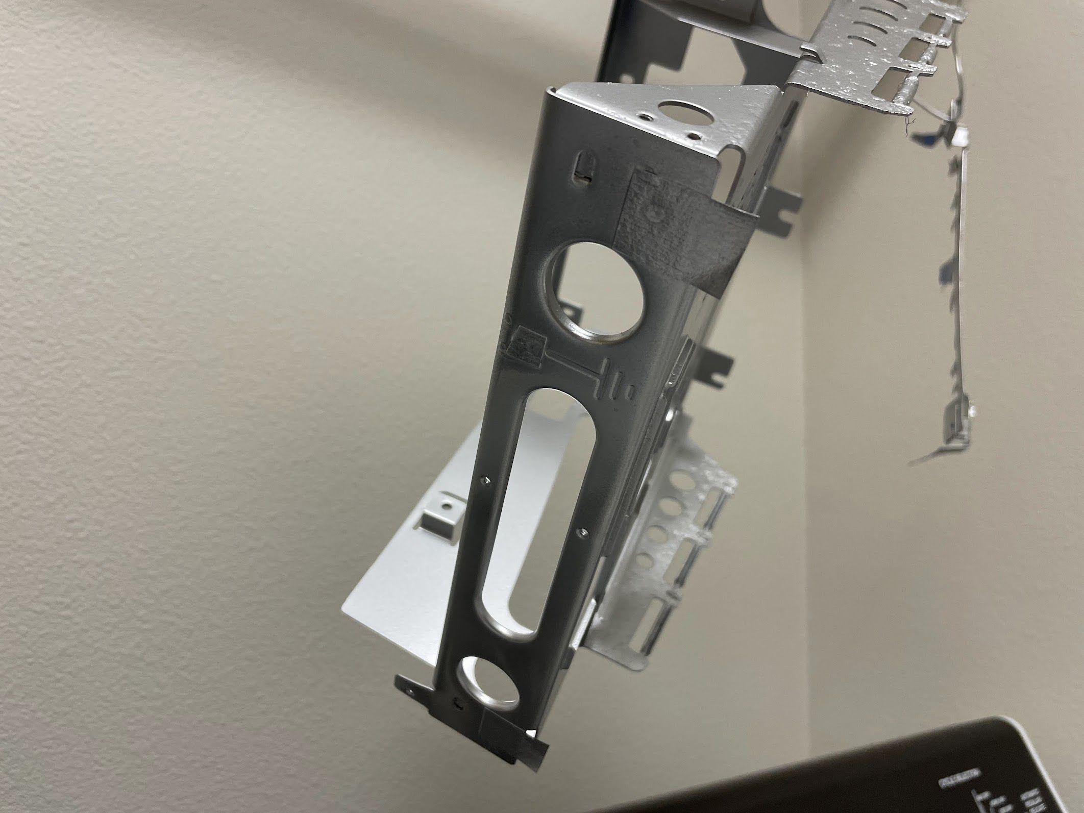
Next, I desoldered the shield from the logic board. Do you see where this is going yet?

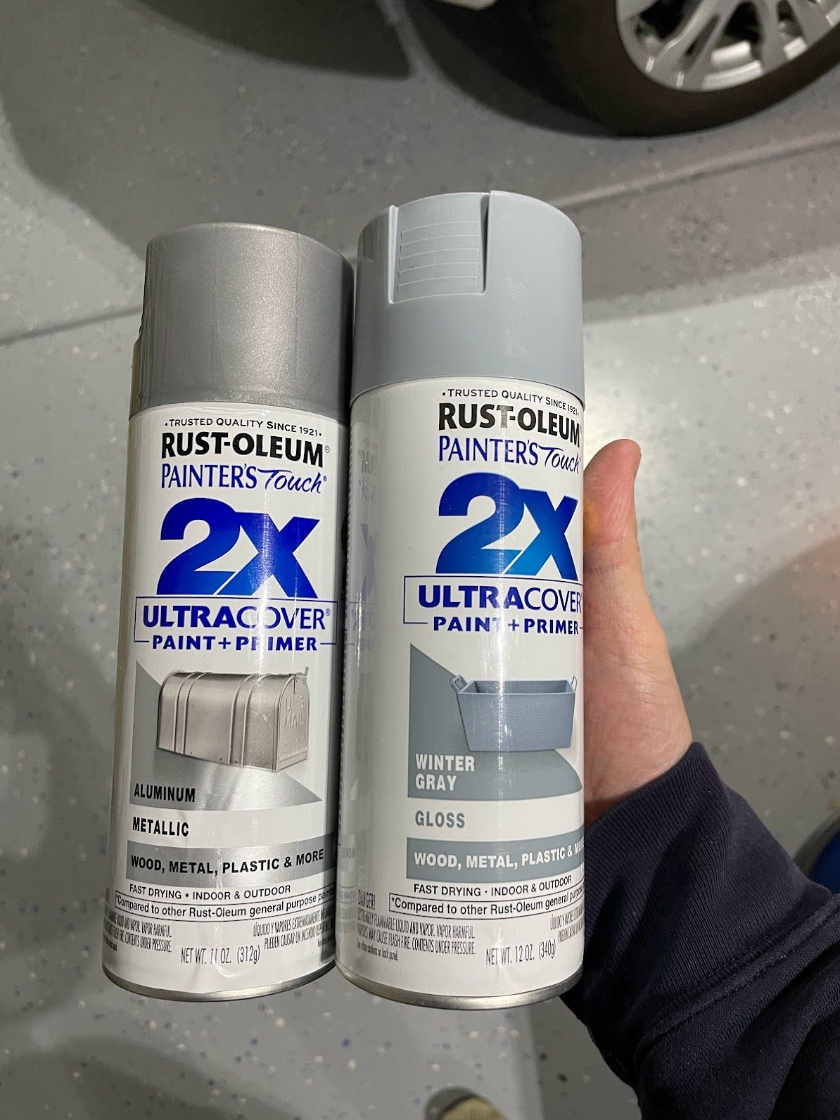
The blue chassis just wasn’t working for me. I had to paint it. I had to. I grabbed a couple of cans of paint at Home Cheapo, and ultimately chose the Metallic Aluminum Rust-Oleum 2X.
I found a place to hang them up in the back yard, and hit them with their first coat of paint.
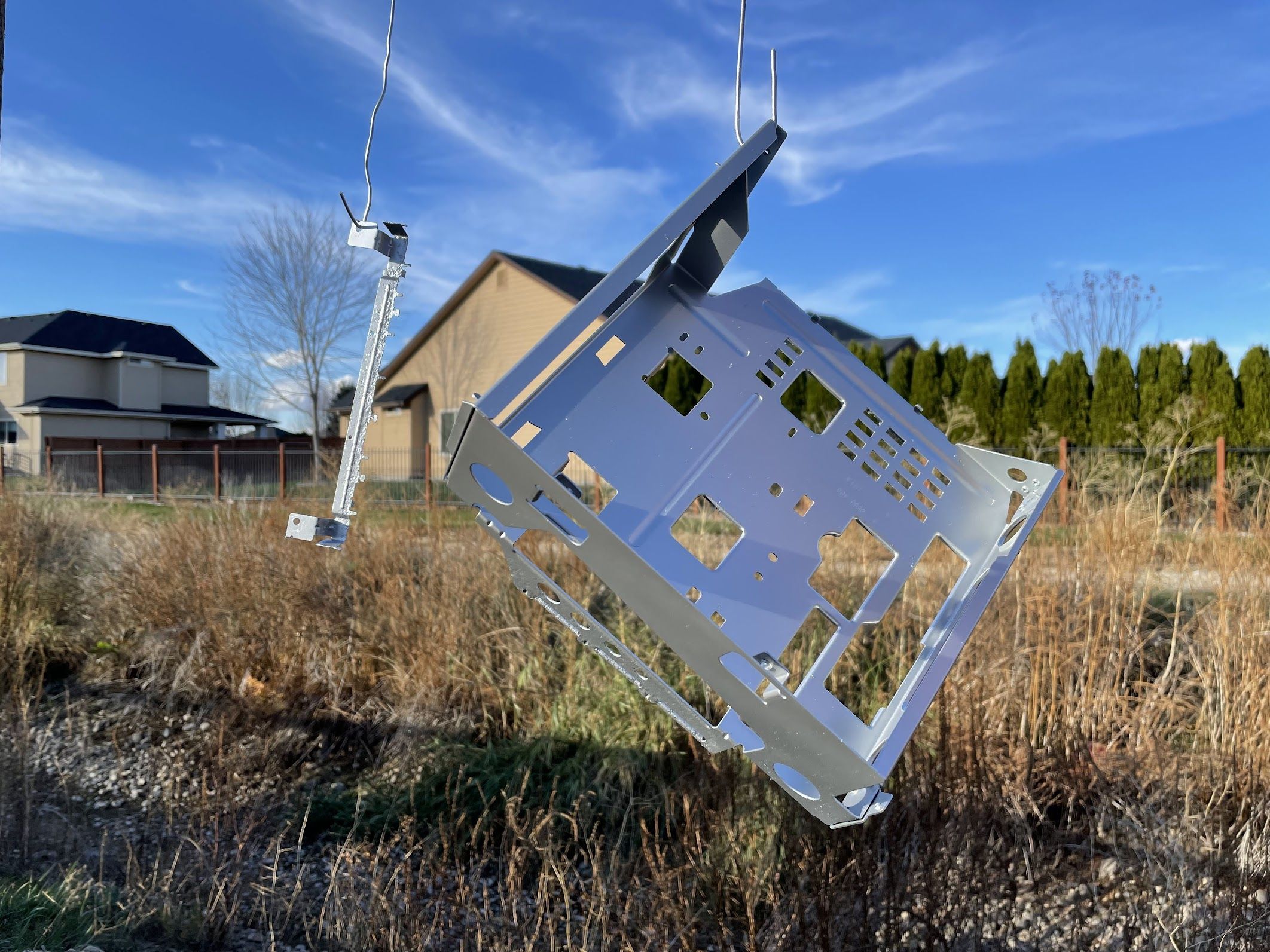
Since it was pretty cold outside, I took them straight inside and hung them up in the laundry room.
In my excitement, I forgot to mask off some important places for grounding, so after things had dried overnight, I hit some places with the wire wheel and some 220-grit sandpaper.
I masked things off, and hit both parts with a couple more coats of paint.
I’m really, REALLY happy with how these turned out!
fter it had a couple of days to dry, I put everything back together, including soldering the shield back on the logic board (again). As for masking and grounding, I only worried about three points:
- Where the ground wire attaches from the analog board
- The two places where the logic board shield touches the back of the chassis
Other than maybe the floppy drive, I couldn’t find any other places for grounding. I also checked for continuity for grounds everywhere, and it all checked out. Considering that you can easily run these machines outside of their cases on a bench, I think this will be 100 percent fine.
Finally, I installed the BlueSCSI. Since I stole the hard drive bracket for my SE/30, I just used a couple pieces of double-side tape on the back of the BlueSCSI bracket.
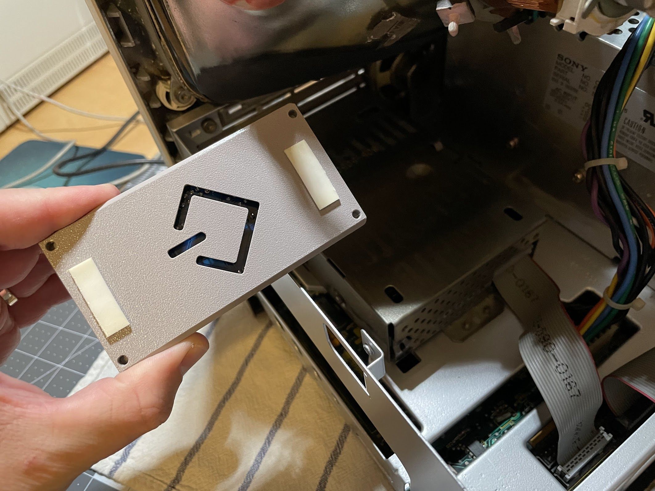
Then, I stuck it to the top of the floppy drive bracket.
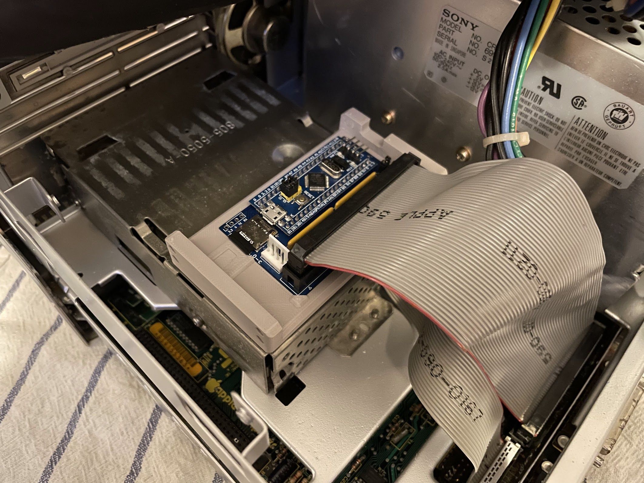
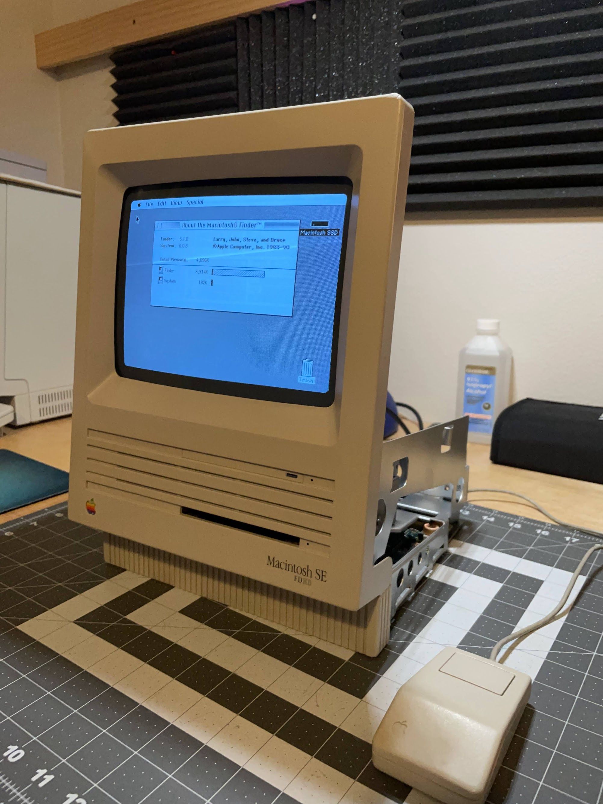
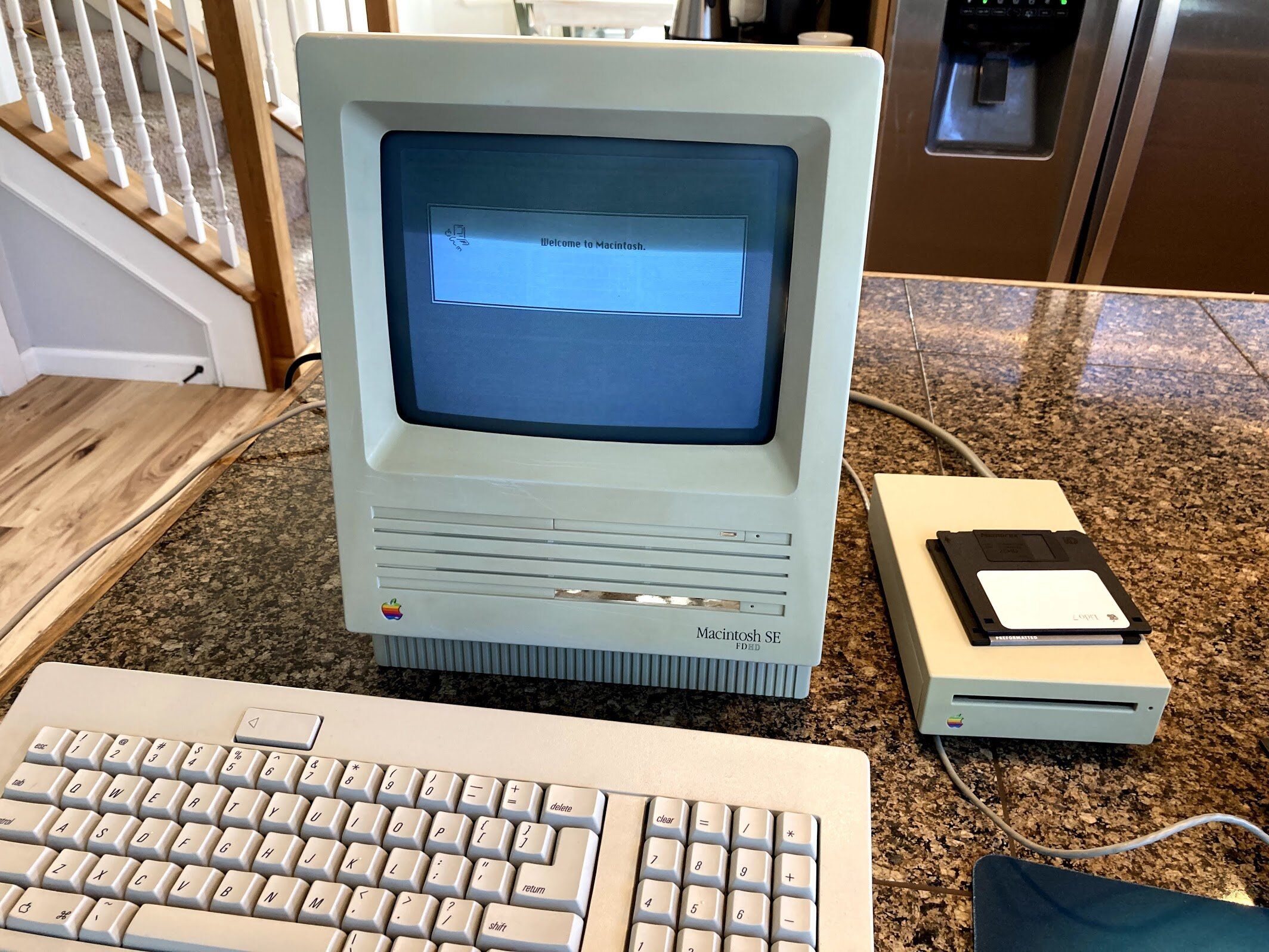
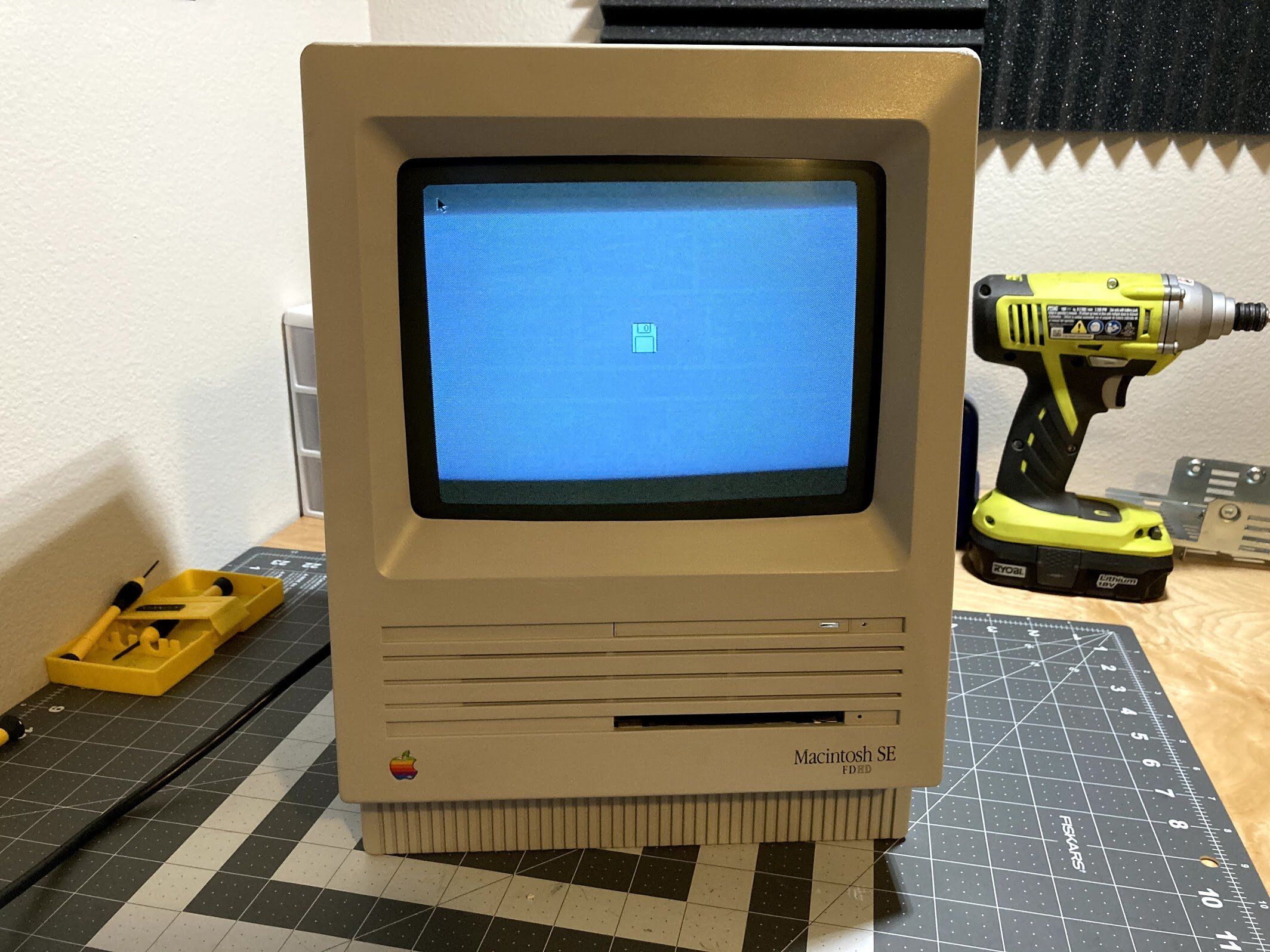
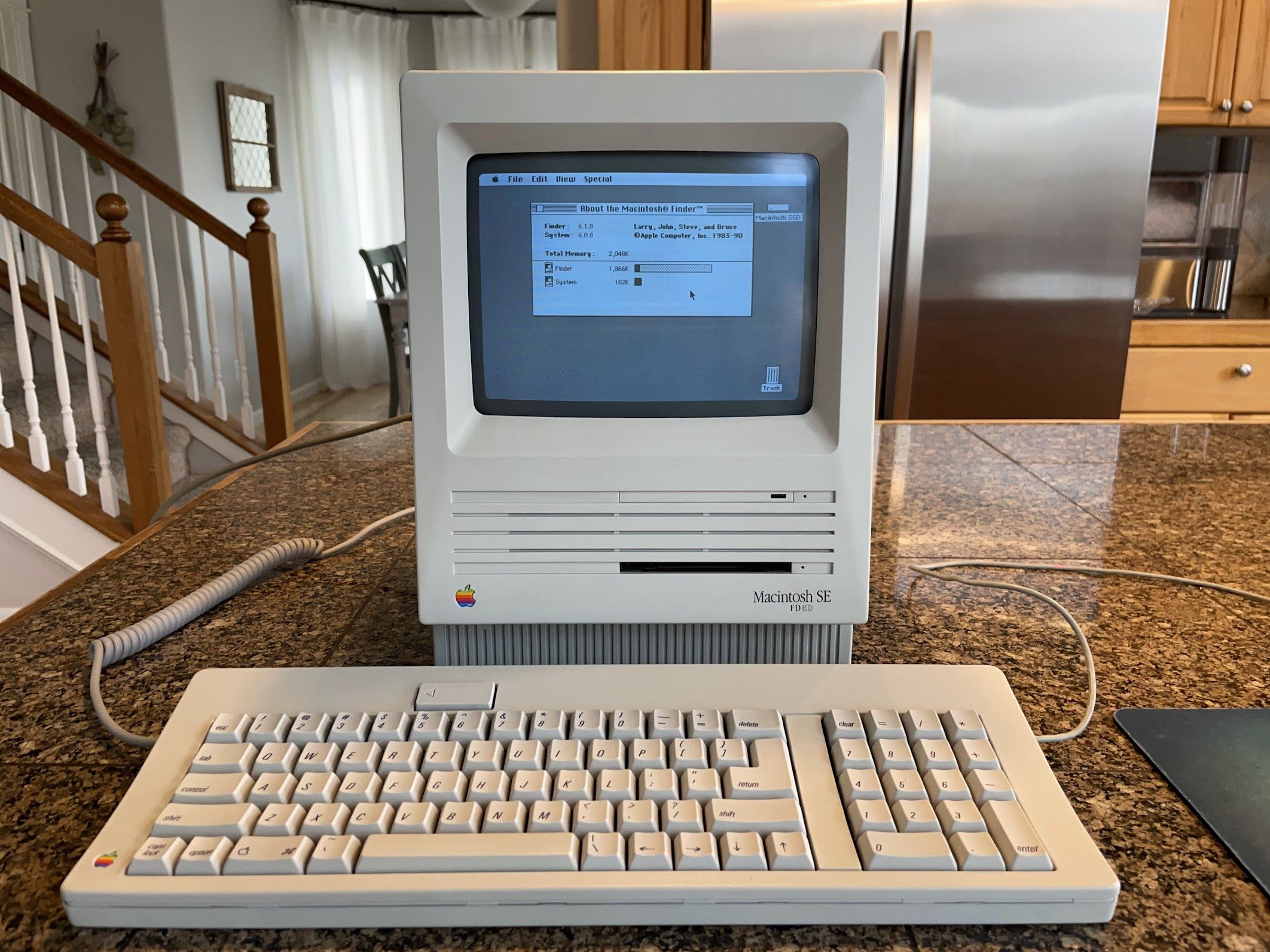
We’re just about done here. After installing the BlueSCSI, I flipped the power switch, and the machine booted right up to System 6.0.8. Fantastic.
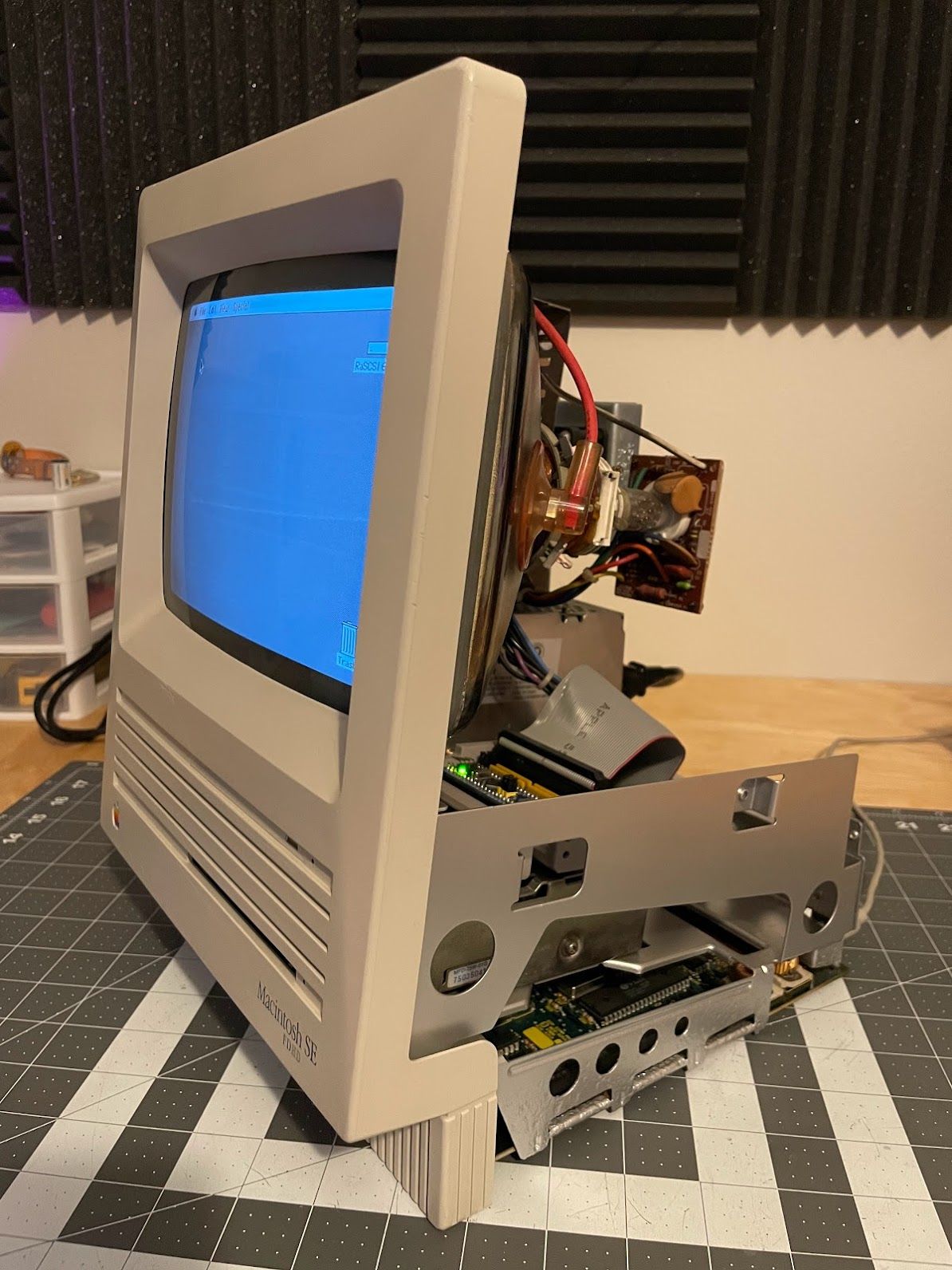
The CRT was positioned slightly too far to one side, so I used a plastic spudger to rotate one of the centering rings. With that, the restoration was done.
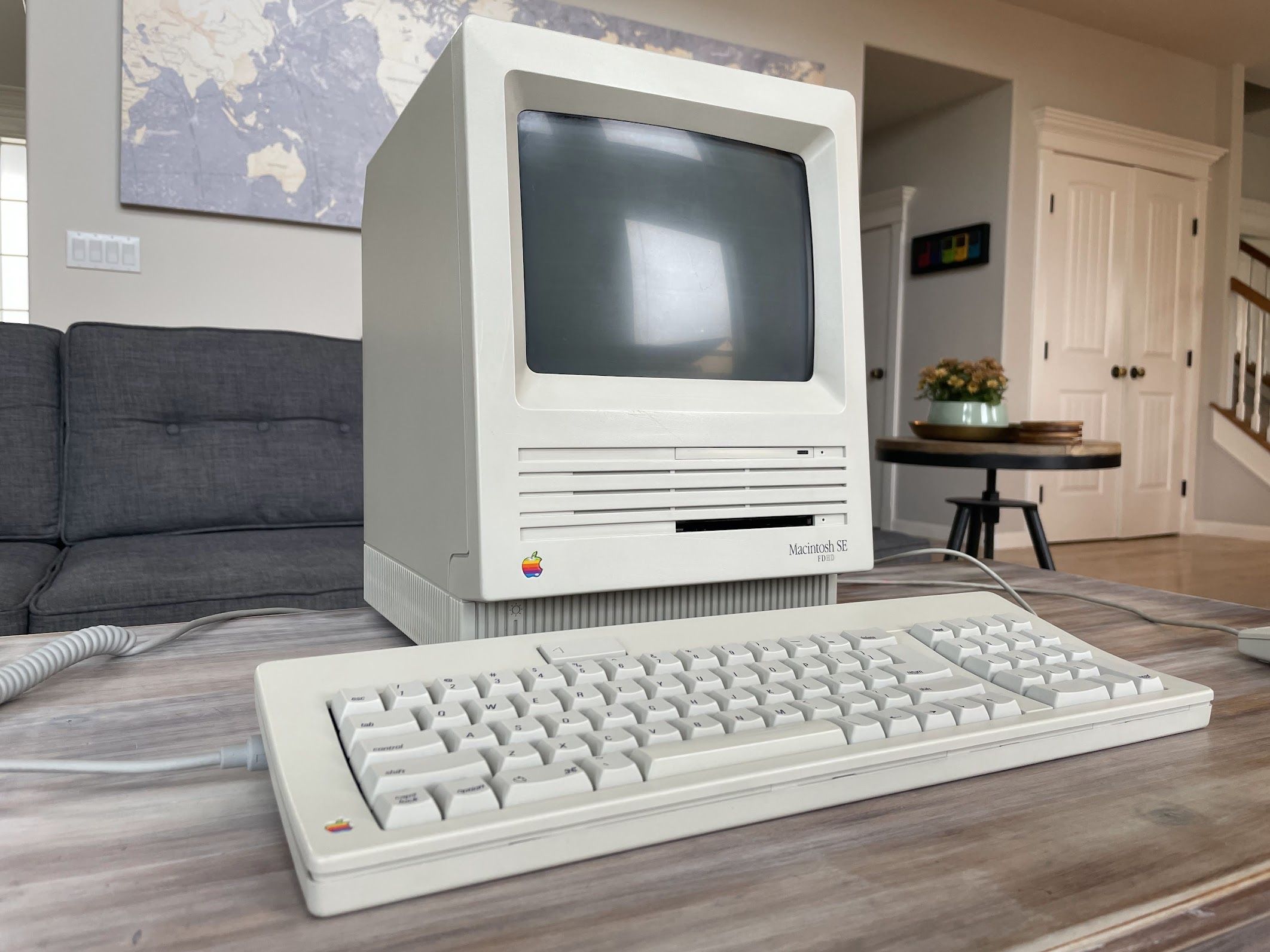
Results
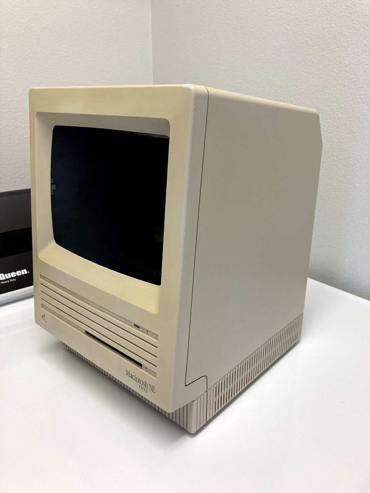
Let’s take a look at the results! Here is before:


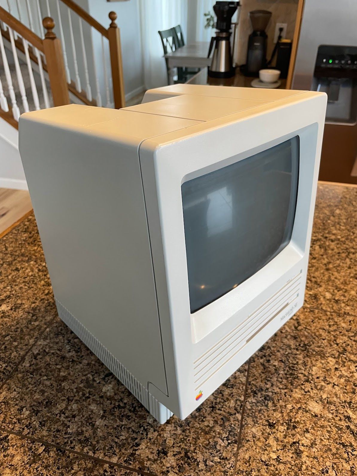
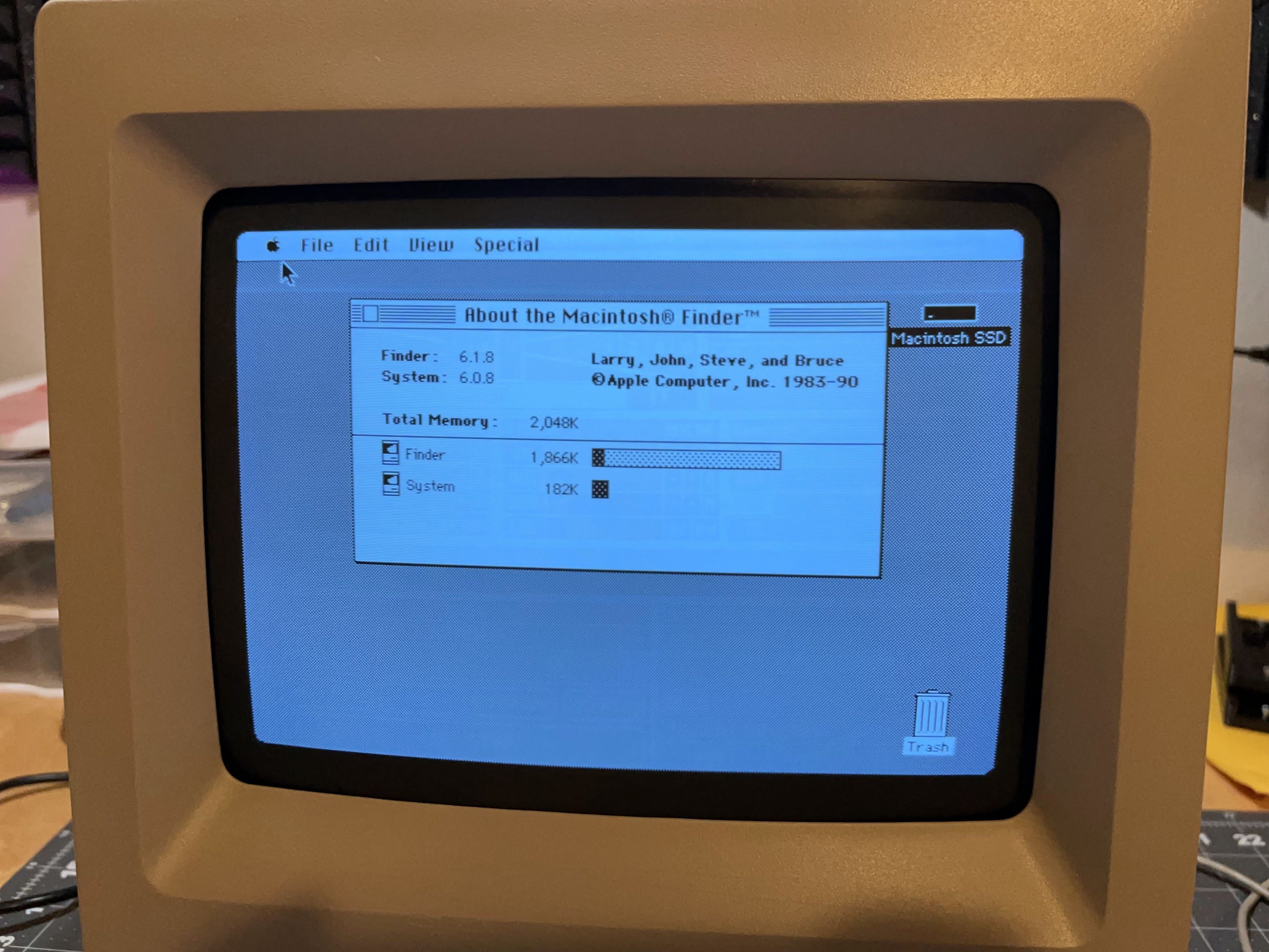
Up until now, I hadn’t thought to see how much RAM it has. It appears to have 2 MB. In this configuration, System 6.0.8 will be super snappy, and it will work great for some black-and-white Mac gaming. If someone wanted to upgrade it to 4 MB, and plug in a PiSCSI or newer BlueSCSI for SCSI Ethernet emulation, you could probably download some files with FTP, or even do some Telnet! Technically, you could load up a webpage or two… but with System 6 and a 4 MB RAM ceiling, that would be a bit challenging.
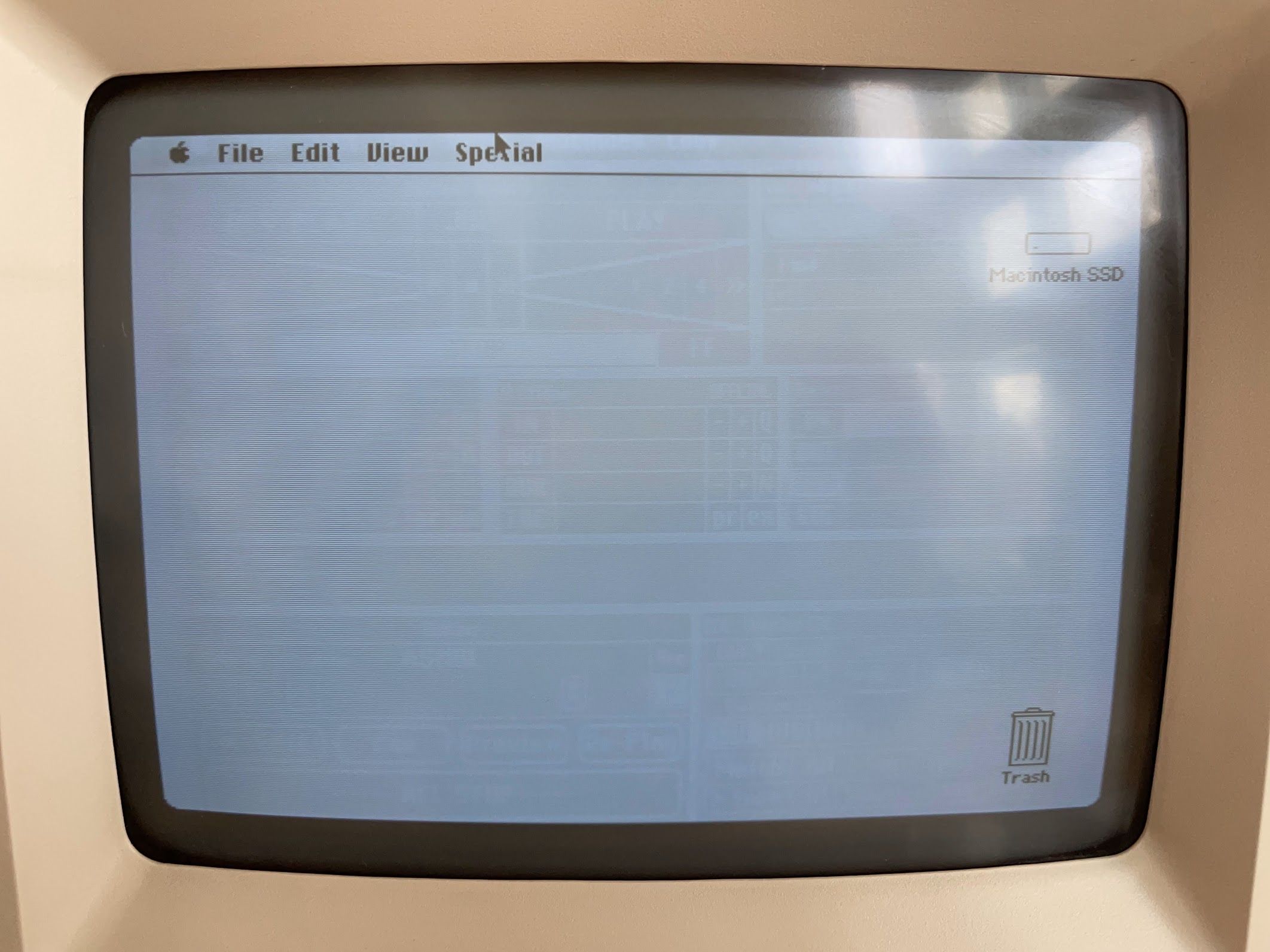
Yes, there’s some burn-in… but I don’t think it’s very distracting. This is max brightness in a well-lit room - not super bright, but really no brighter than I go on my other machines.

Here’s a close-up of the burn-in. I can’t quite tell what application it is.
And I think this is where our restoration thread draws to a close! As for the machine’s future - I’m going to offer it back to the person who gave me the whole pile of Apple stuff to begin with (although I would need to track down a mouse and keyboard for it). The floppy drive still isn’t super reliable, so I might tinker with that a little bit more. For now, thanks for reading my restoration thread! I hope you enjoyed it.
Epilogue
You might remember from earlier that this machine came equipped with 2 MB of RAM. On seeing that, my friend Daniel donated a 4 MB RAM upgrade for the machine!
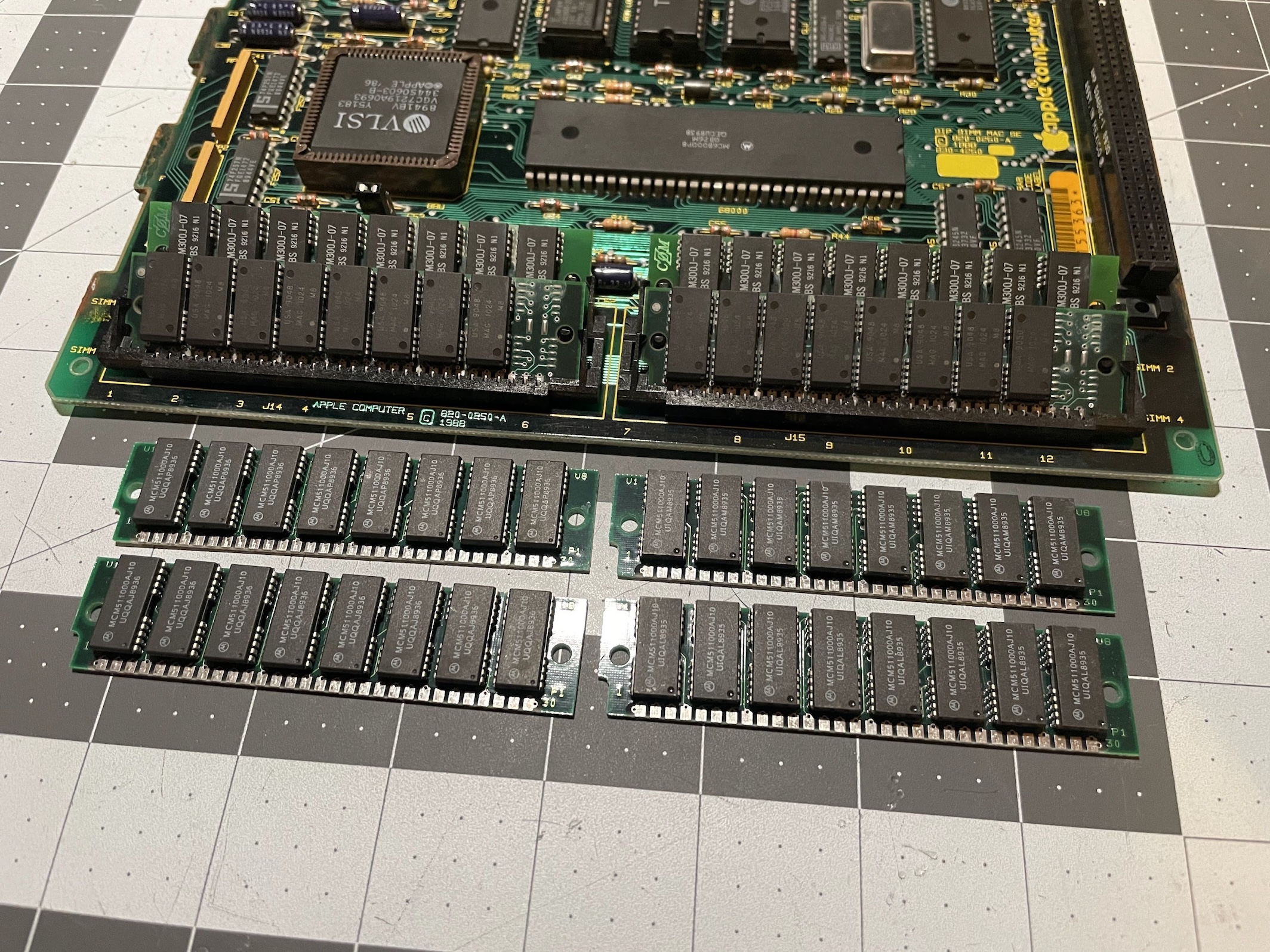
I scrubbed all of the contacts with Isopropyl alcohol, and installed them in the machine. The tabs on the slots are all plastic, and one is broken, so I really wanted to only install the RAM once time to avoid breaking things.
As for telling the Mac how much RAM to look for, this Macintosh SE FDHD is of the jumper variety. There is a 1 MB position, and a 2/4 MB position. Some Mac SE’s (probably older non-SuperDrive and non-FDHD versions) use resistors that you have to remove.
When I booted it up, I was very confused to find that only 2 MB of RAM was detected.
I consulted the Low End Mac Macintosh SE RAM Upgrade guide, and immediately found my mistake.
To upgrade to 4 MB, remove all four 256 KB SIMMs and replace them with 1 MB SIMMs, being careful not to damage the SIMM sockets. If you have the resistor motherboard, remove R35 and R36. If you have the jumper motherboard, remove the jumper. (Oddly, you do not set it to the 2/4M setting.)
Of course, removing the jumper did the trick.
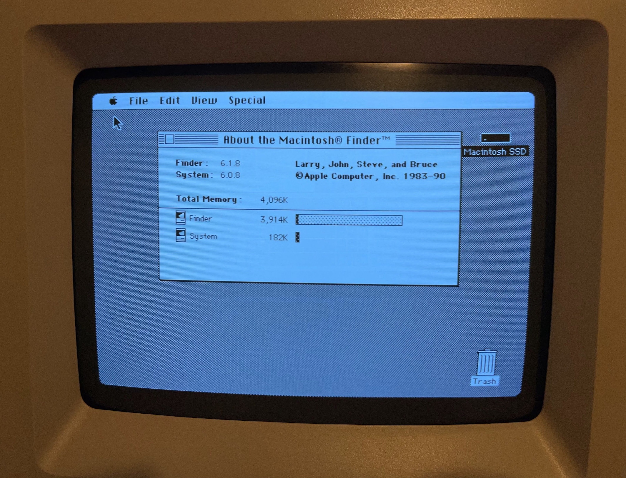
And with that nice RAM upgrade, this Macintosh SE FDHD is “maxed out”! Sure, I could find a Shiva Ethernet PDS card for it, or one of those neat accellerator PDS cards, or maybe even install a RaSCSI! But with a 1.4 MB floppy drive, solid-state storage with the BlueSCSI, and 4 MB of RAM, this little Macintosh SE has become quite the capable little machine.
Thanks again Mark for the upgrade!