Nintendo Entertainment System Restoration
I originally wrote and posted this restoration log on TinkerDifferent, but have decided to duplicate all of my restoration logs to my blog for centralization. While I updated this post on 2025-07-09, the original restoration was completed in 2022. Thank you very much to TinkerDifferent for hosting my restoration log.
Introduction
A NES popped up on Facebook Marketplace for $29. I couldn’t resist! When I handed the seller his $30, he asked, “Wait, don’t you want your $1 in change?”
I grinned and said, “Nah, don’t worry about it!”
I felt like I got a REALLY good deal! Let’s see if that turns out to be true.
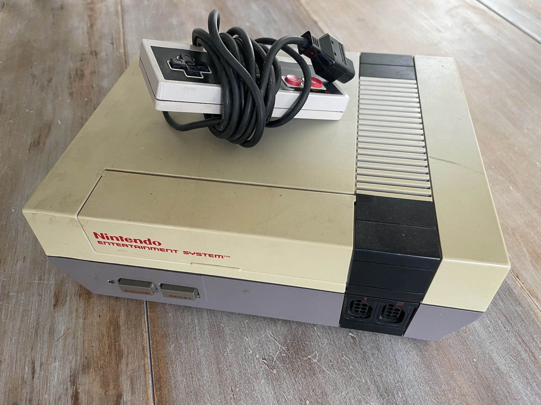
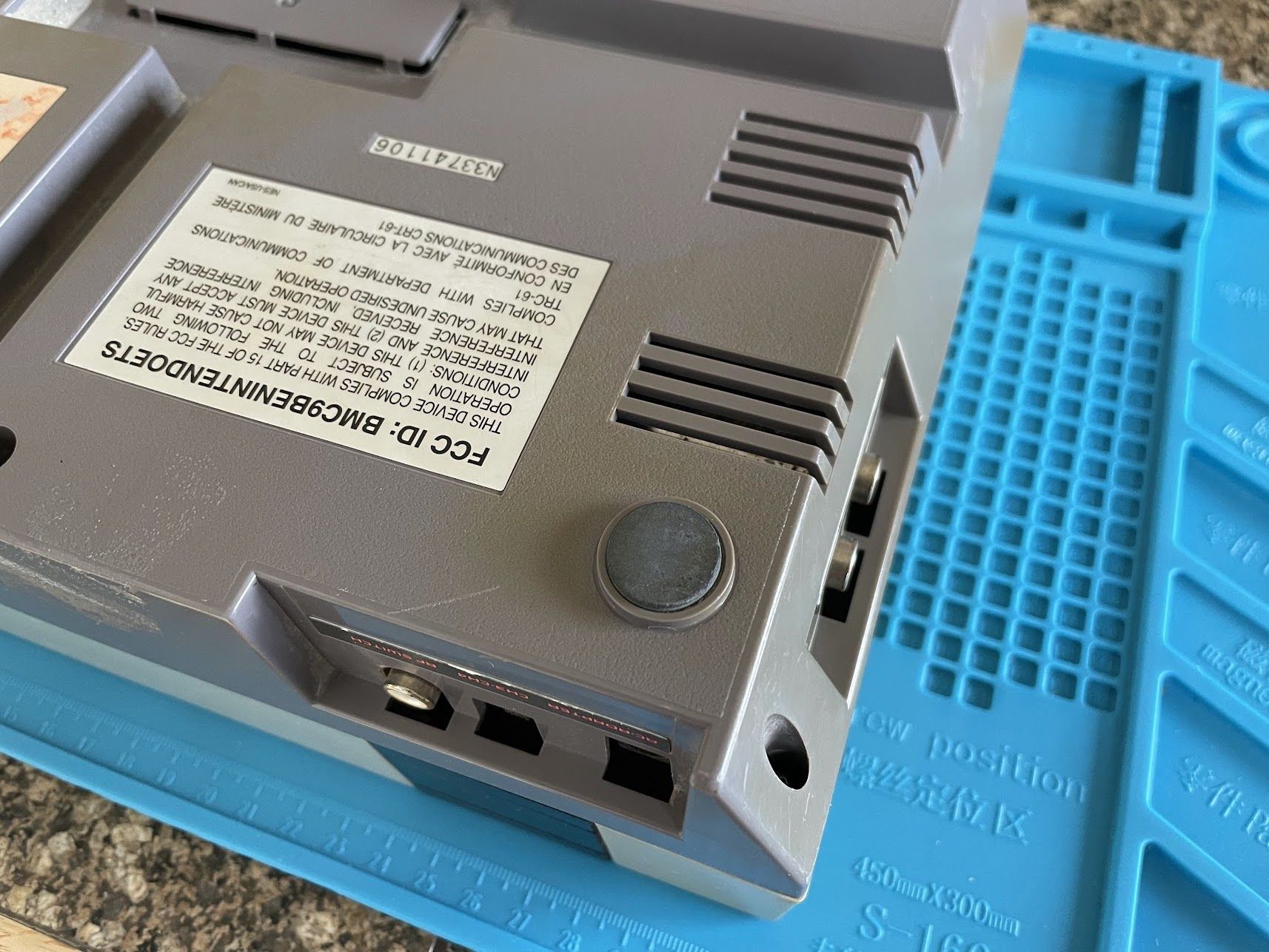
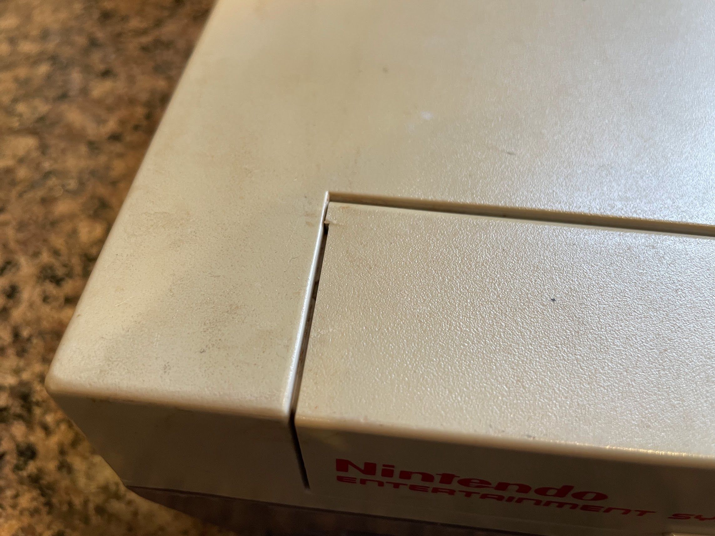
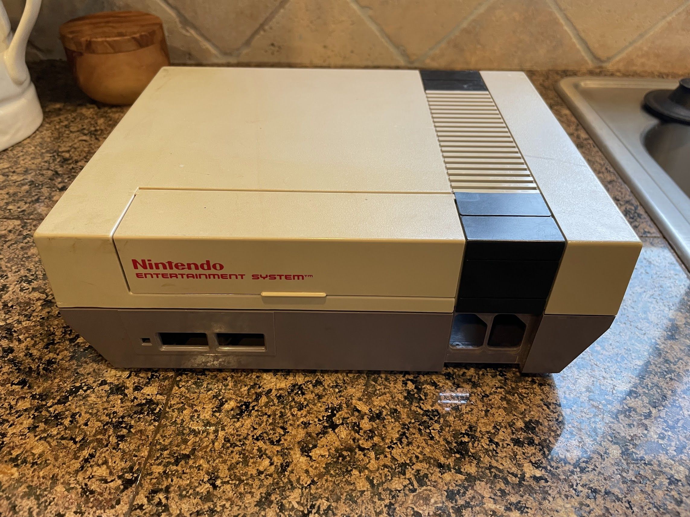
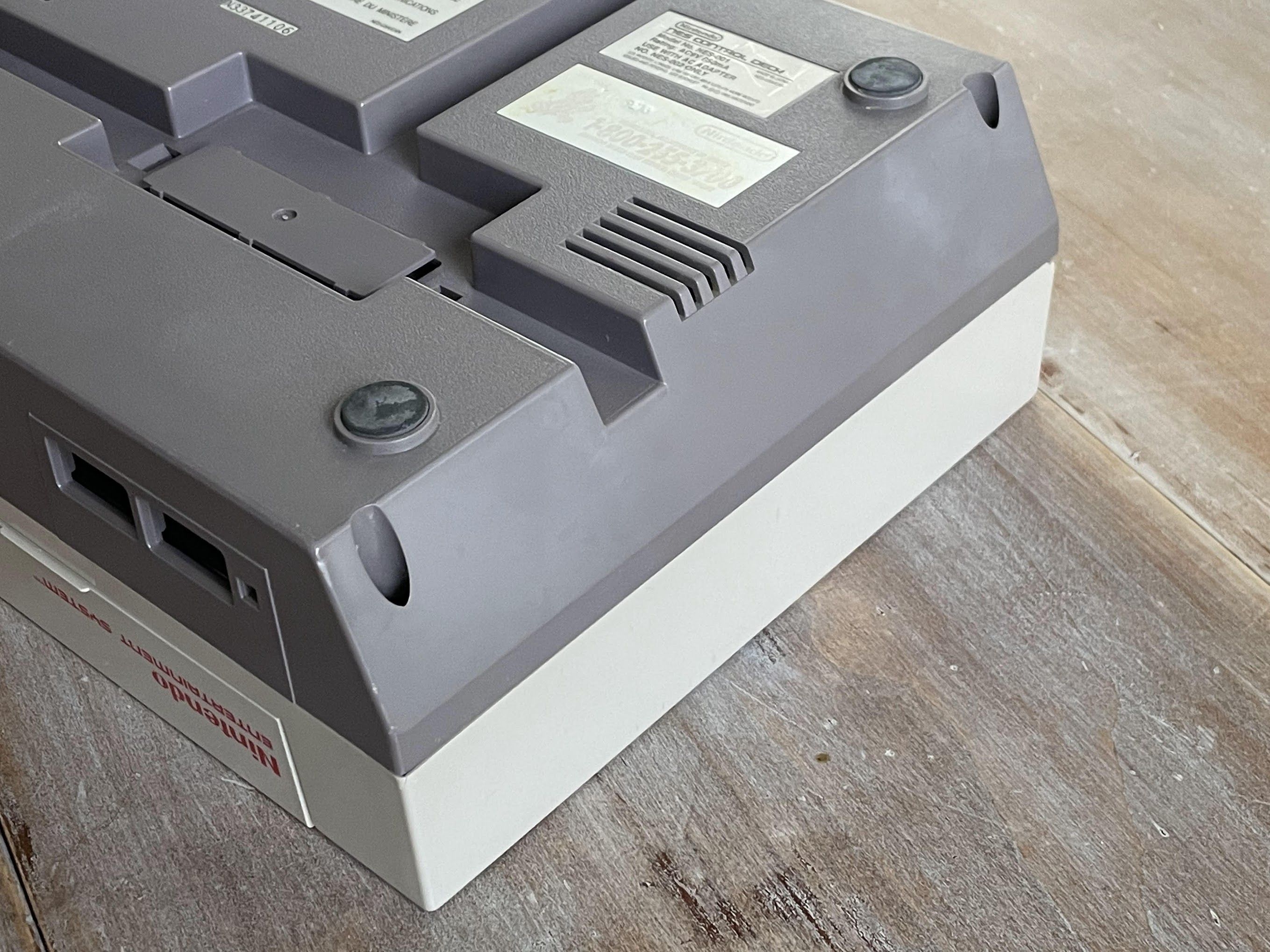
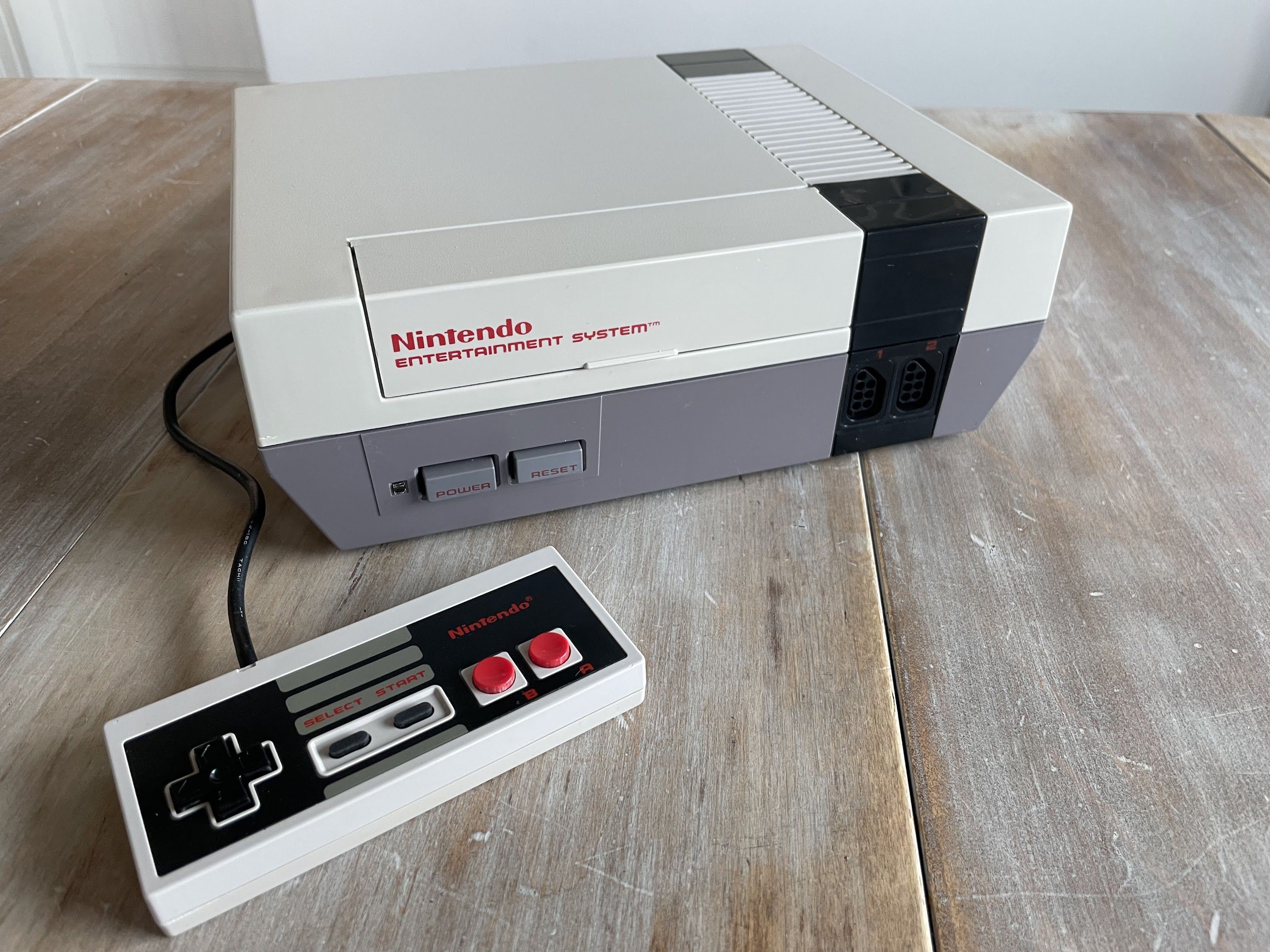
It came with a 12v power adapter, which I think these can technically handle… but I still plan to replace it with a proper 9v power adapter. I don’t want to risk burning out the voltage regulator. Overall, the console is in good shape, but it’s very yellow and dirty.
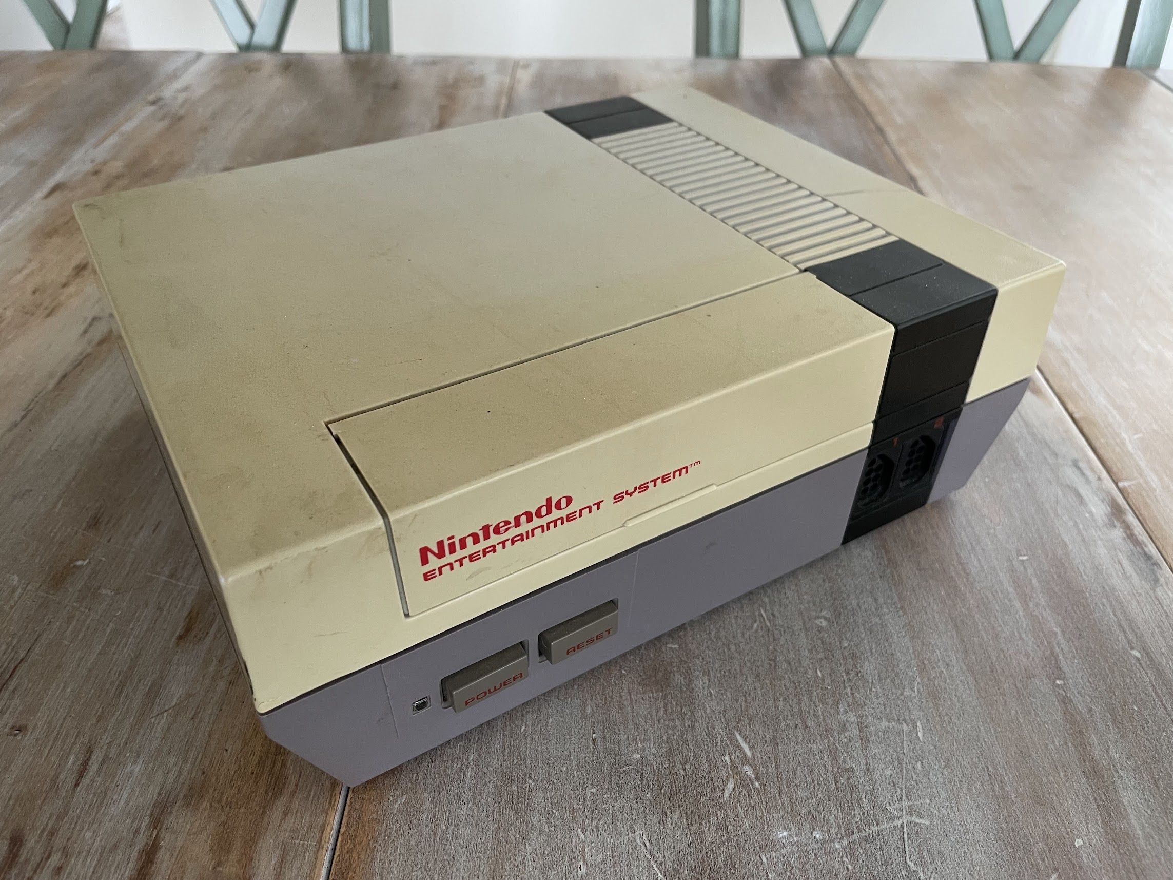
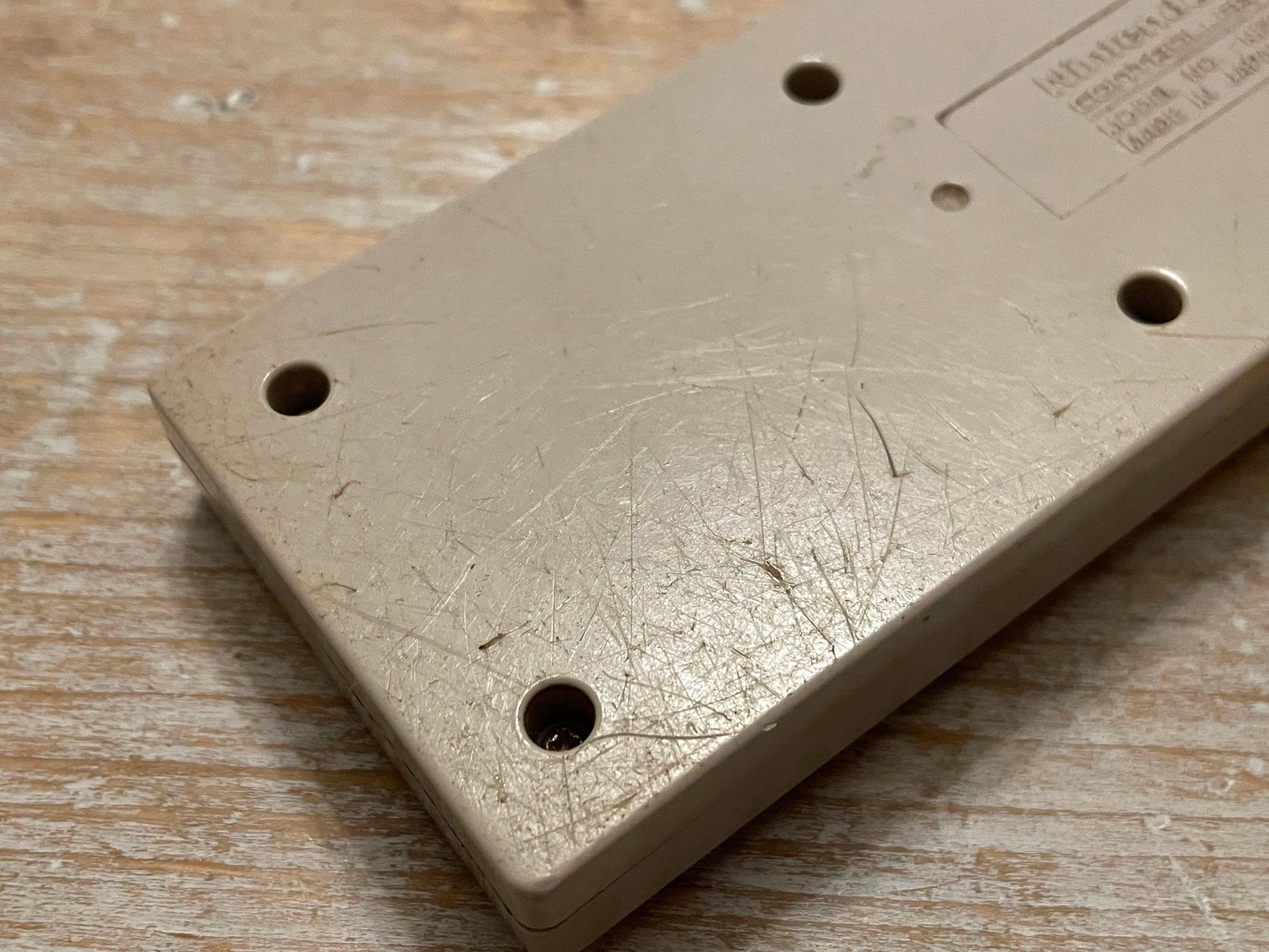
Of course, the yellowing on the top didn’t surprise me, but it was present on the bottom as well.
Disassembly
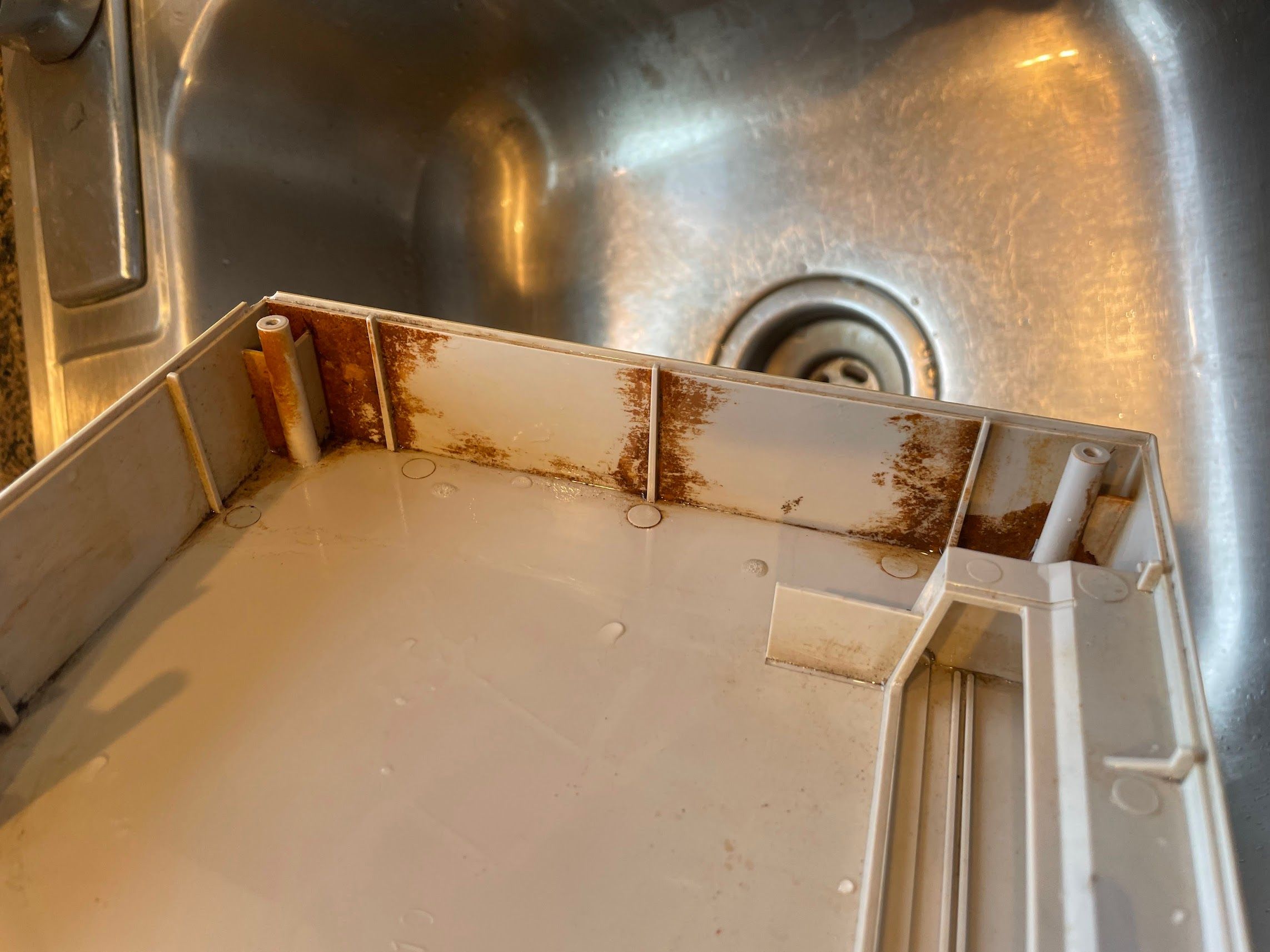
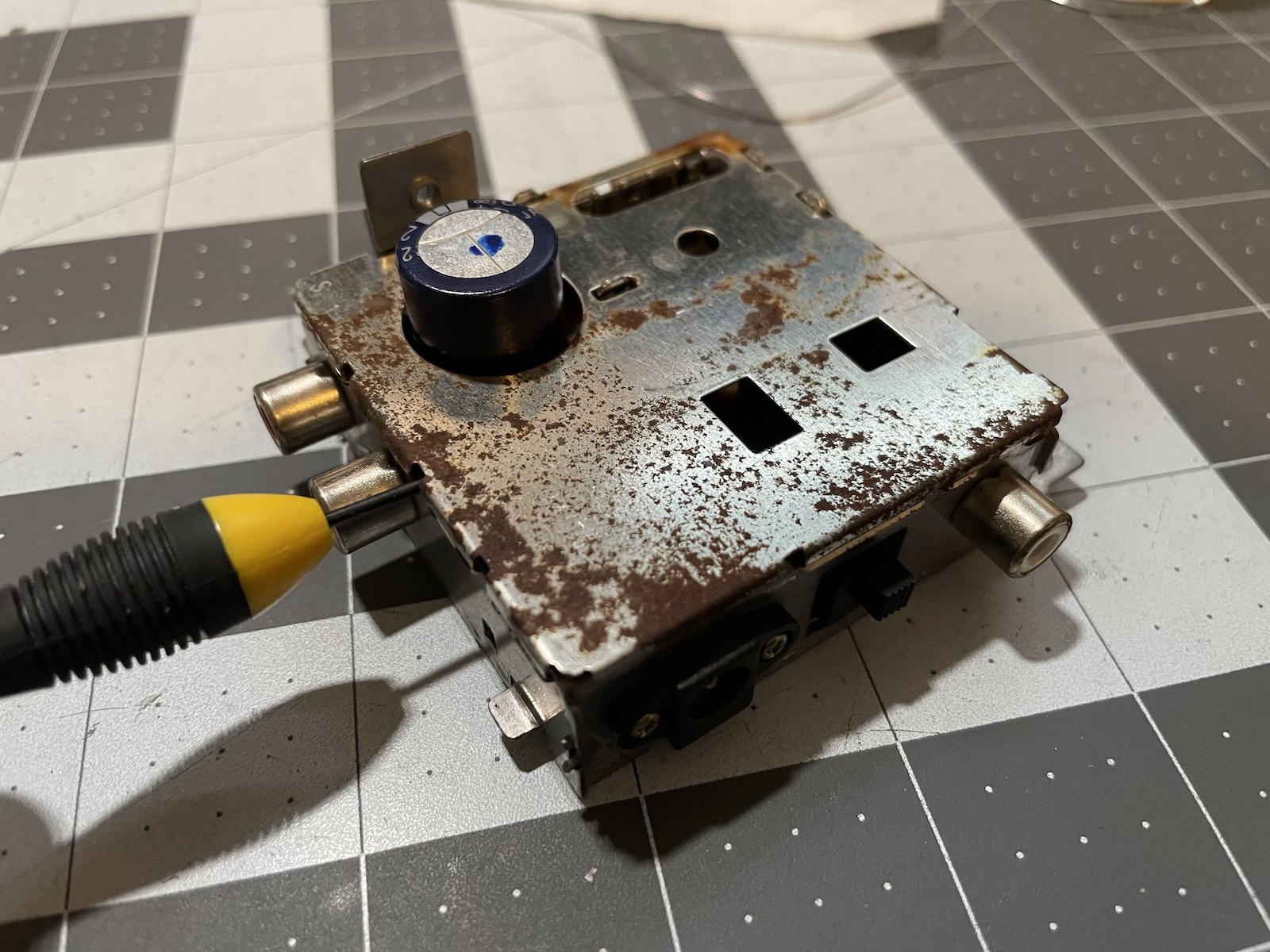
I started to take it apart, and quickly found signs of moisture damage. I think this console might have spent some time enjoying the outdoors.
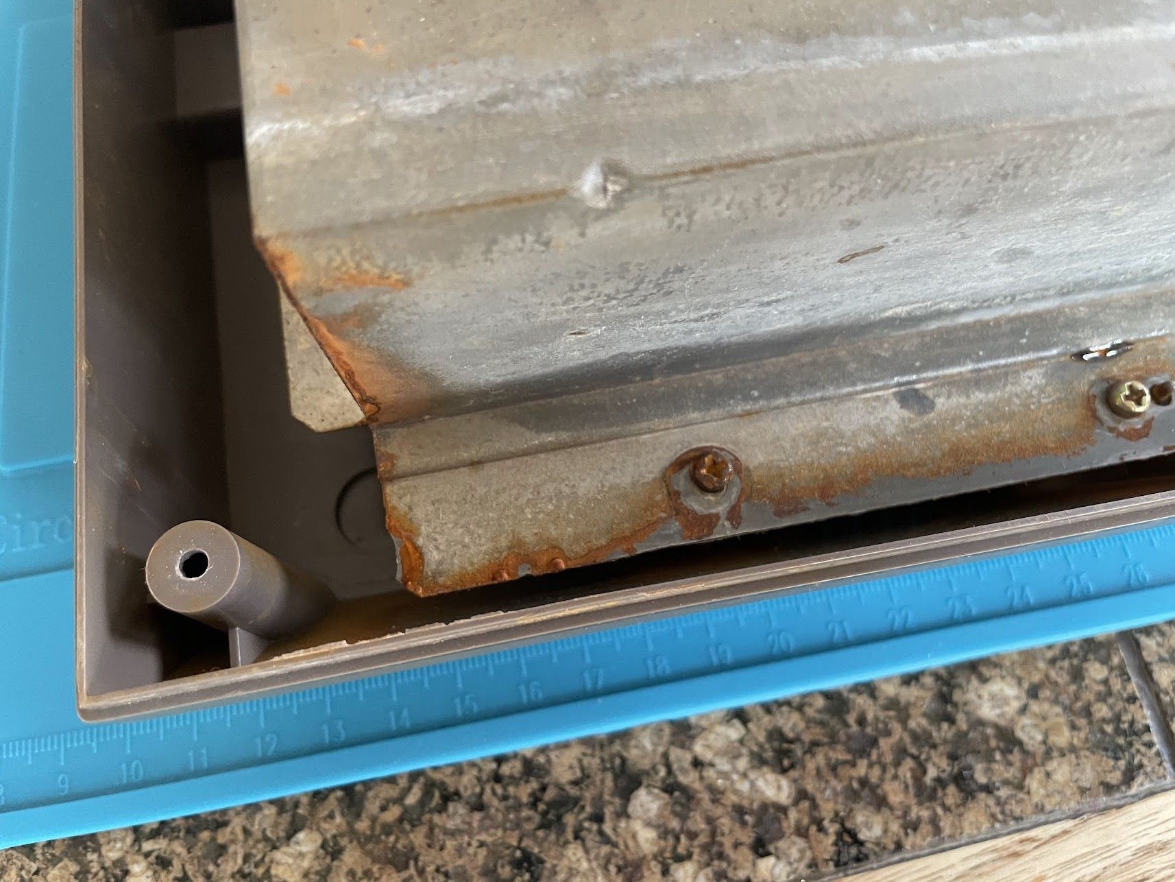
Luckily, the rust seems to be mostly limited to the main shields. There’s a bit more on the RF shield around the video and power circuitry, but it’s not bad.
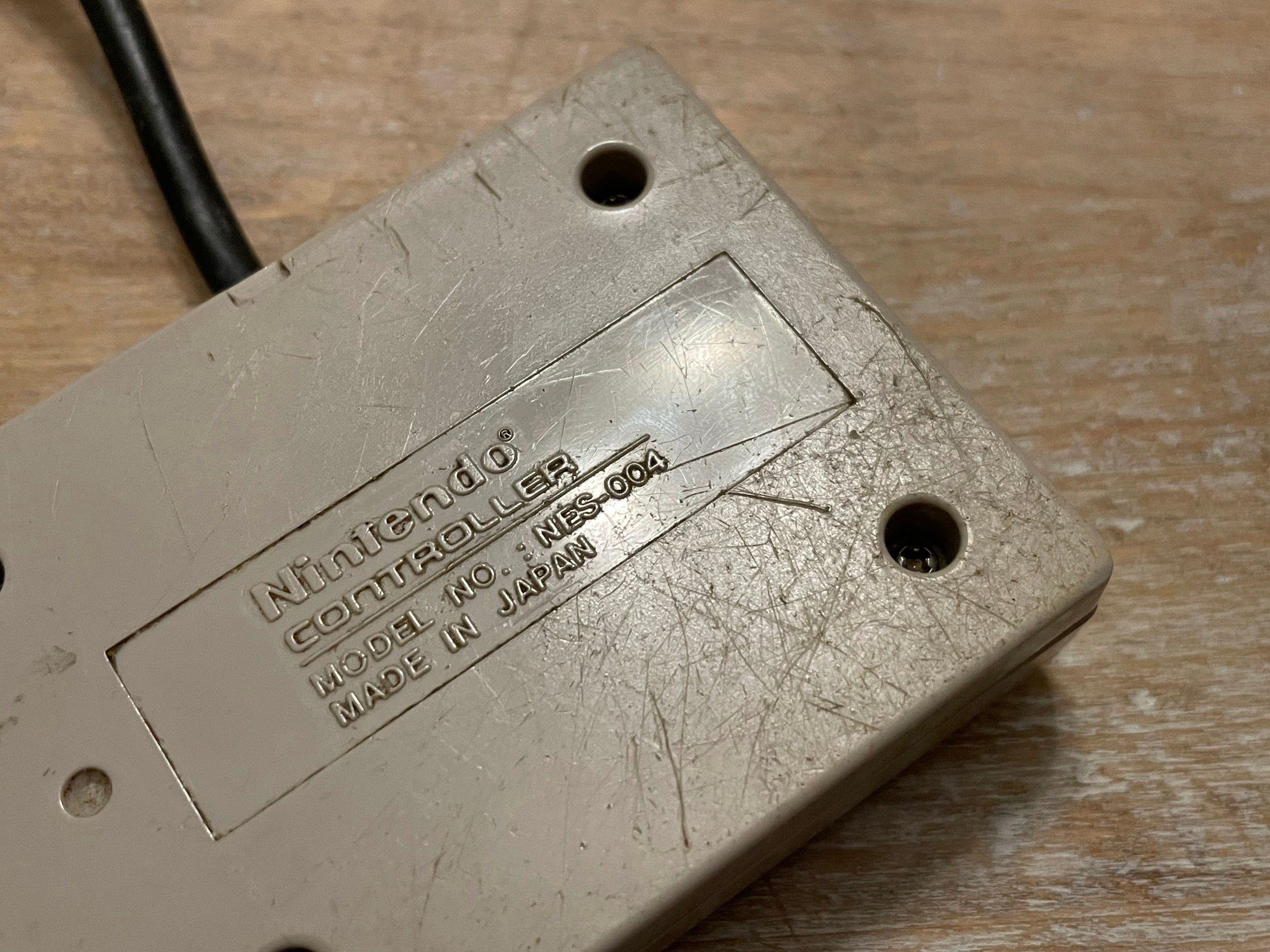
I noticed that this screw on the right hand side of the console was slightly backed out. Someone has been in here before…
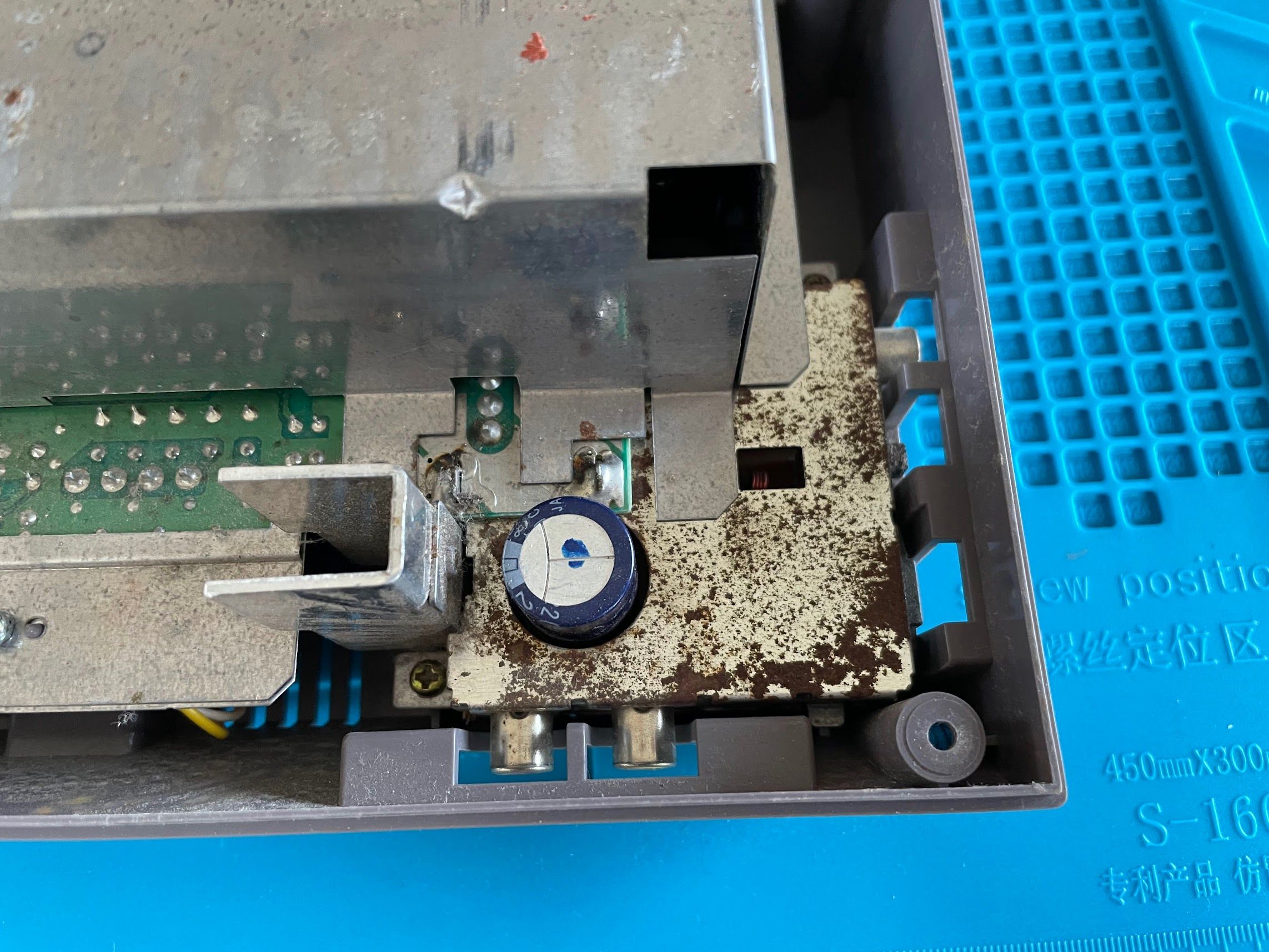
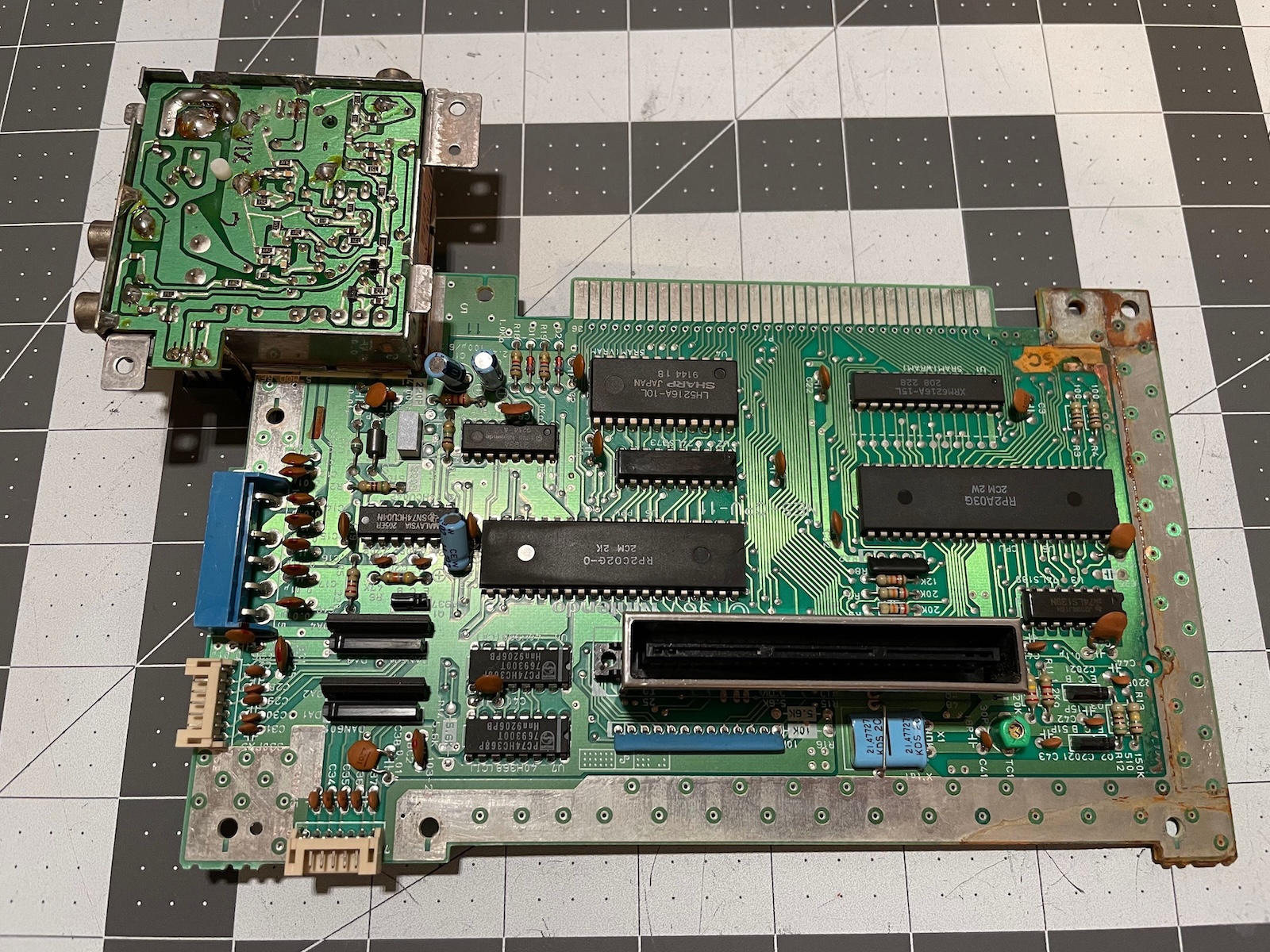
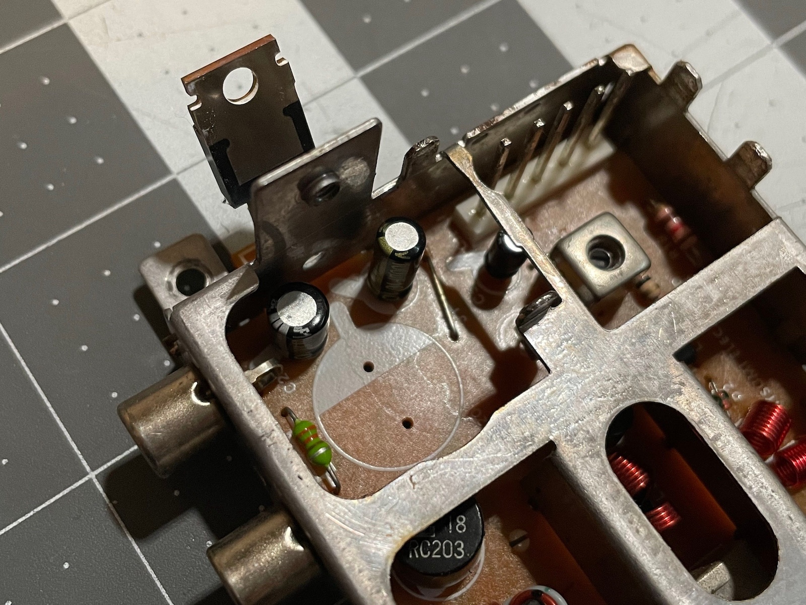
As soon as I had everything apart, I inspected what I had. I think the electronics look pretty good!
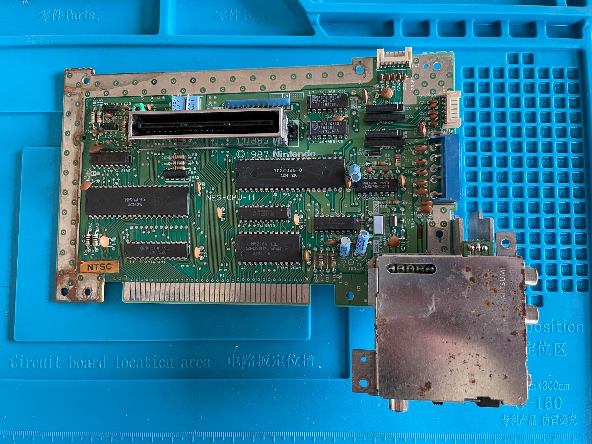
The shields are a bit rusty, but I’ve seen worse.
Connector and Main Board Cleaning
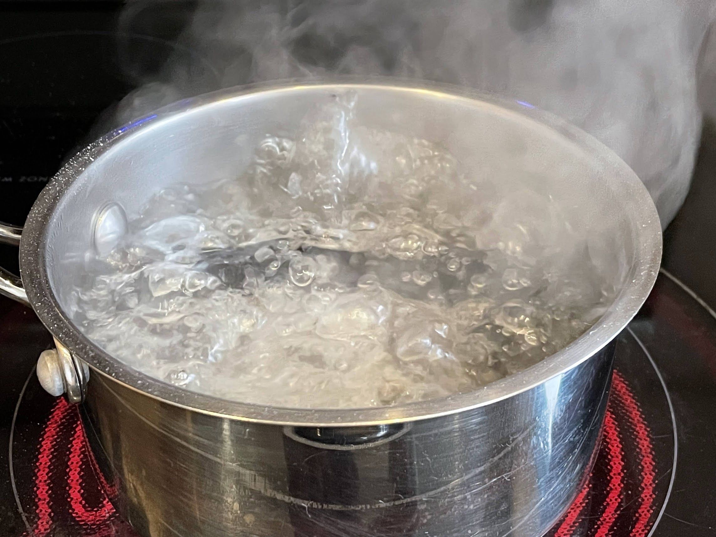
I decided to start by cleaning up the 72-pin connector. I got water to a rolling boil, threw in a dash of baking soda, dropped the 72-pin connector in, and set a timer for 6 minutes. I’ve only done this once before… but wow, did it work. The NES that I did that to is shockingly reliable now.
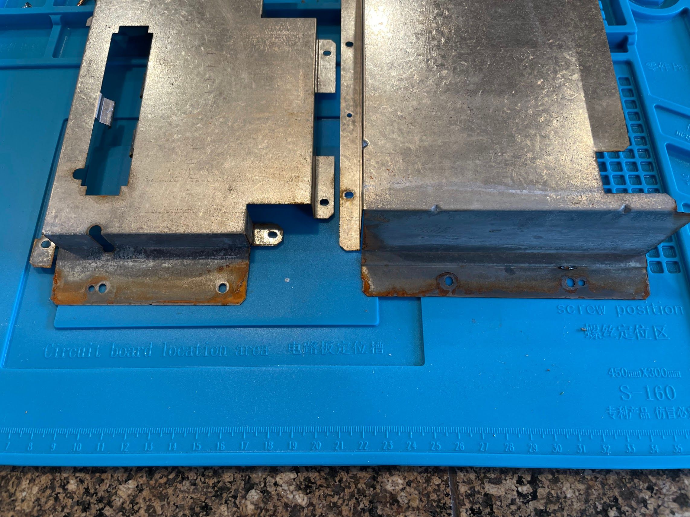
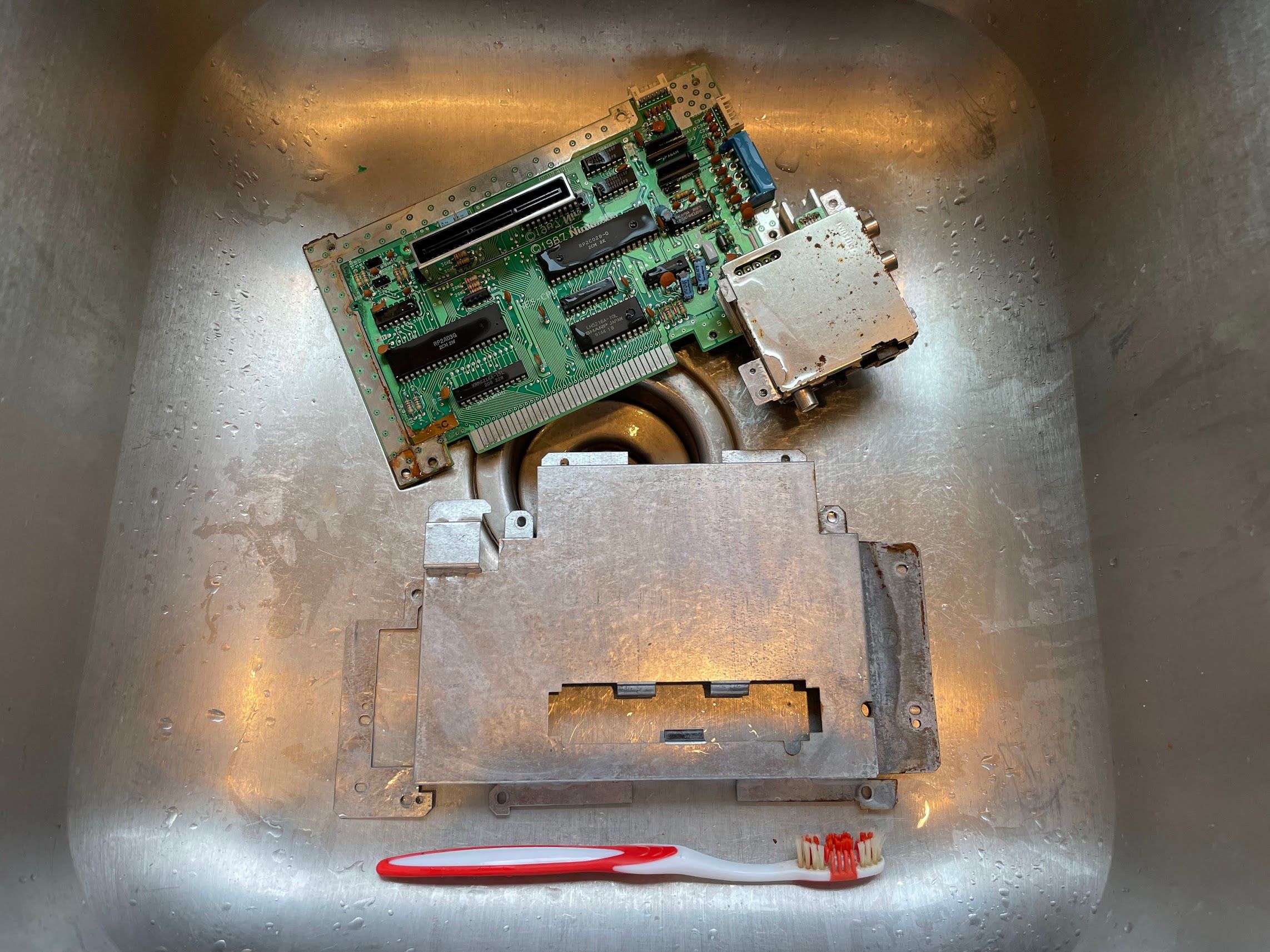
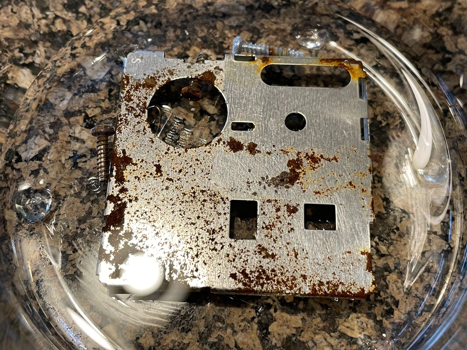
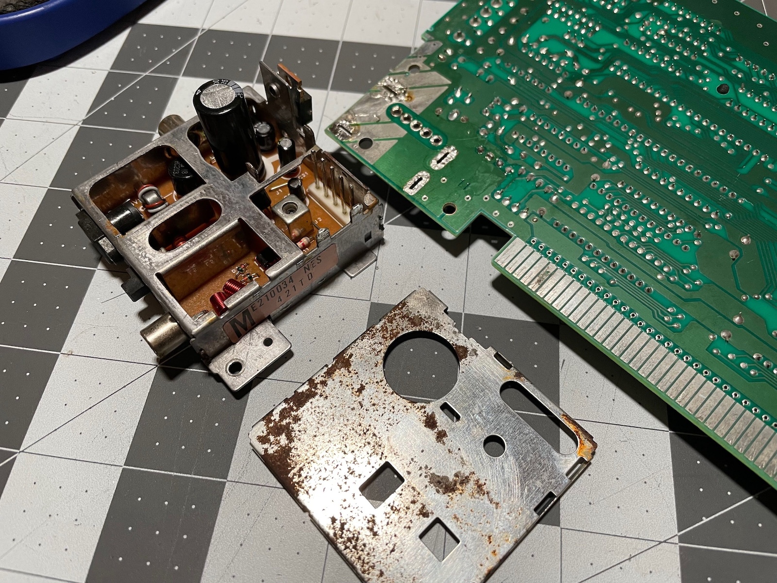
While the 72-pin connector was boiling, I turned my attention to the main board and shields. I attacked the rust with vinegar and a toothbrush. As you can see here, the shields cleaned up very nicely. Nearly all of the rust is gone.As for the main board, I scrubbed it with some vinegar, but spent most of my time scrubbing it with Dawn dishwasher detergent and hot tap water. As soon as I was done, I took it out to the garage and blasted all of the water off it with the air compressor. We don’t want any mineral or soap deposits causing shorts!
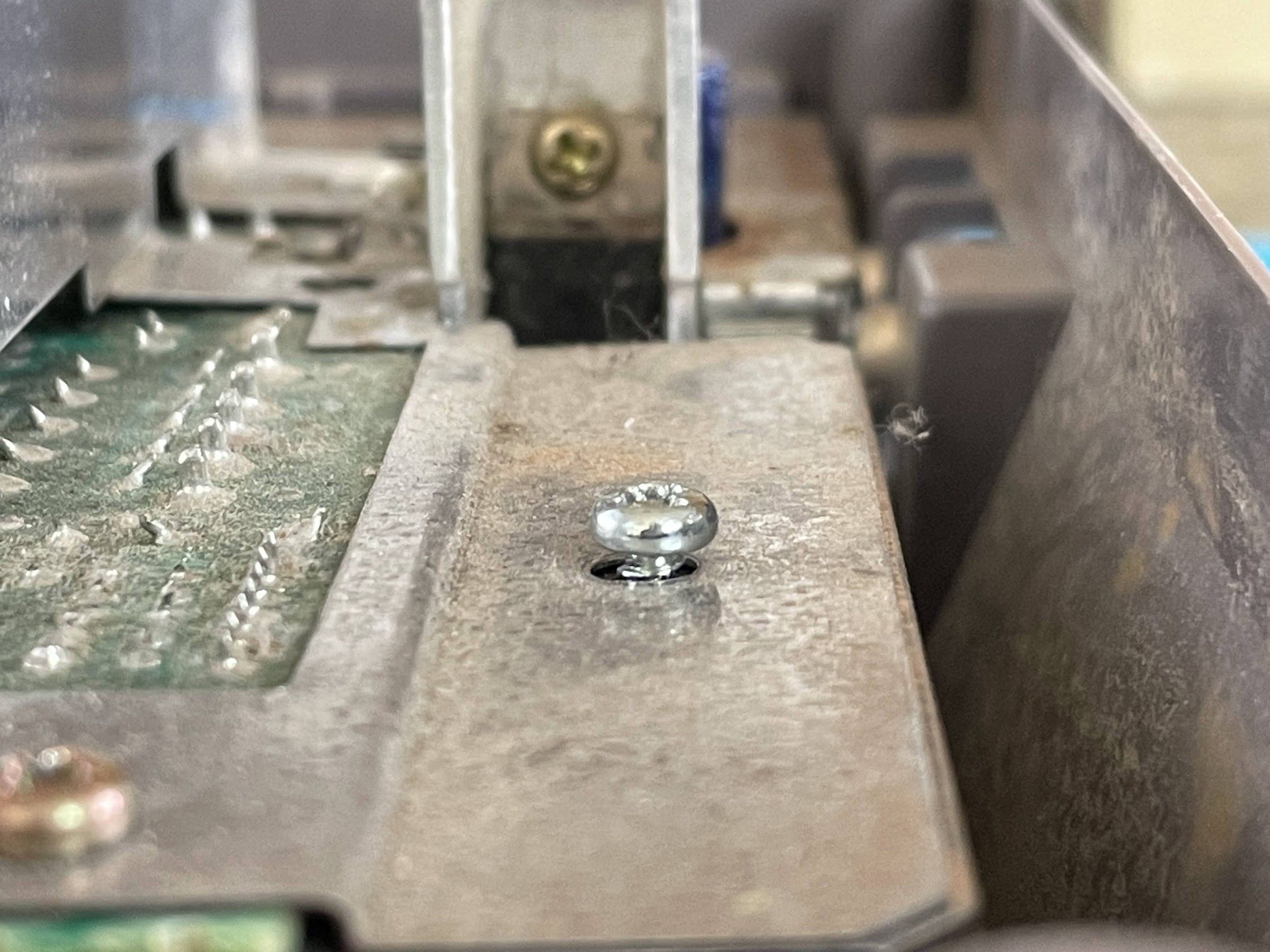
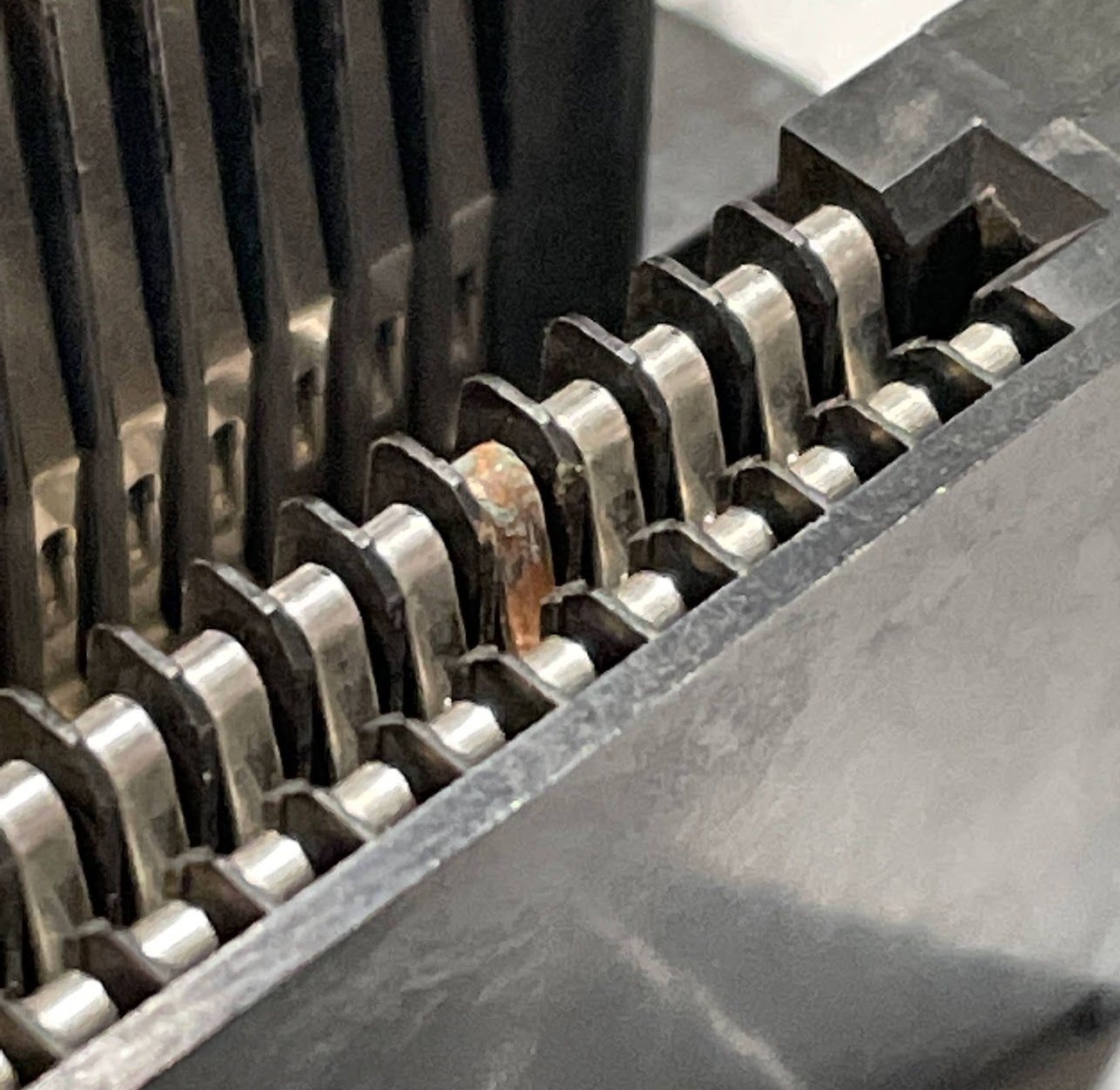
At this point, the 72-pin connector had boiled for 6 minutes. I removed it, rinsed it off, and dried it with the air compressor. Unfortunately, it has a flaw that I hadn’t noticed before:
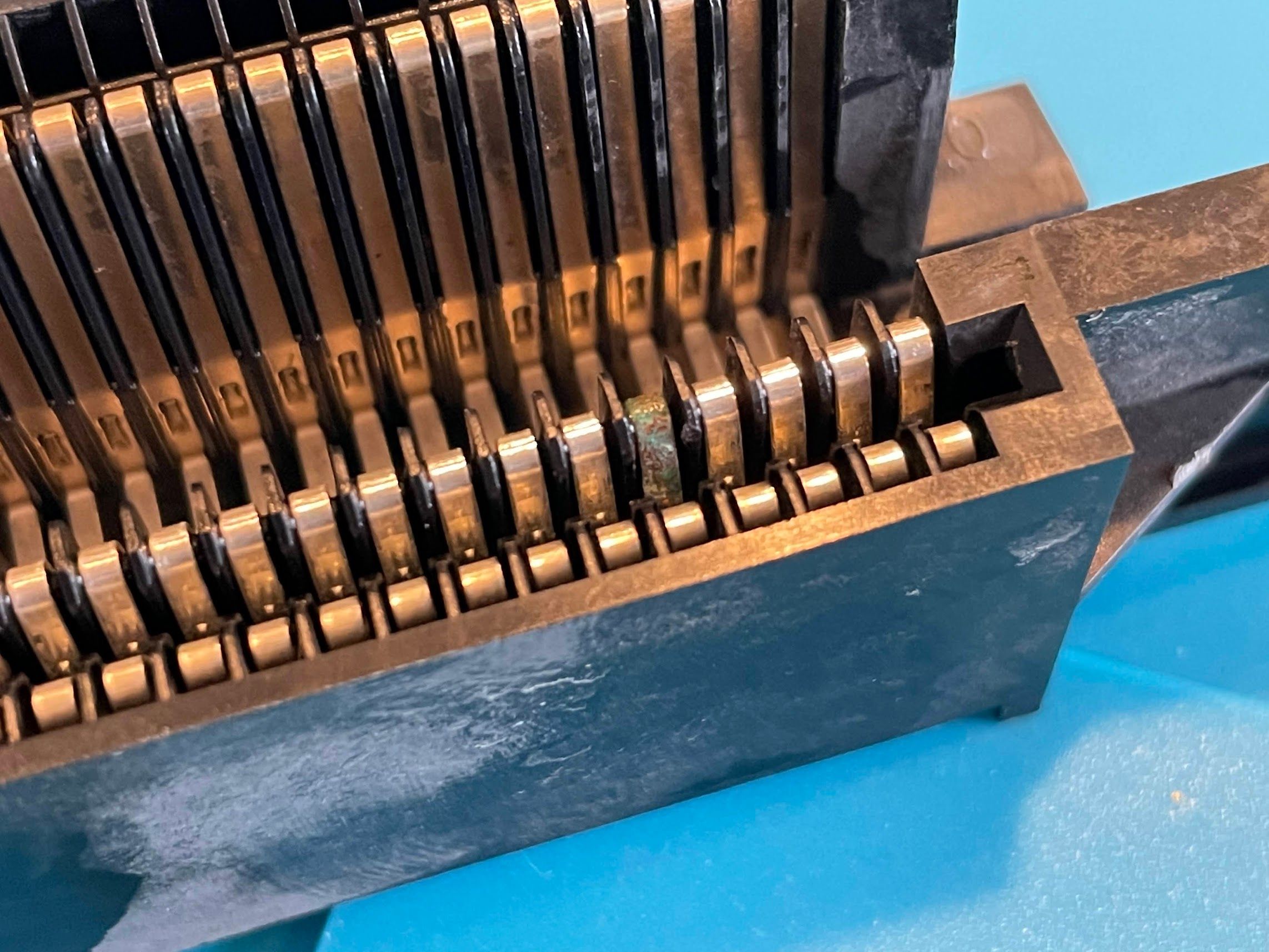
No amount of boiling it is going to fix that. I scraped at the pin with a screwdriver, and quickly decided that I’d need to replace the connector.
It’s well-known that you can buy replacement 72-pin connectors at your local gas station or convenience store, but the design and quality of those connectors is dubious. They’re known specifically for applying a “death grip” to your cartridges, or requiring that the cartridge be inserted in a specific way. That’s just not good enough for me. I asked around on Reddit a bit, and heard two good recommendations:
- Buy a “Blinking Light Win” 72-pin connector. Sadly, these seem to be out of production and are no longer available.
- Buy a refurbished OEM 72-pin connector from eBay, specifically from guaranteed_games. I was able to find the specific listing for the connector, and it was only $13.69 including shipping. That’s just a few dollars more than a cheap-o connector from Amazon! Nice!
Note from the future: Unfortunately, this connector ended up having the same “death grip” issue, as noted by TinkerDifferent user Amblypygid:
Dude, I bought a refurbished connector from the same exact seller 10 days ago and received a connector that has the same tight grip issue you described. The connector works, but it has a really tight grip to it. Considering on just ordering another one. Going to try leaving a cart in for a week or so like you described and hoping it works.

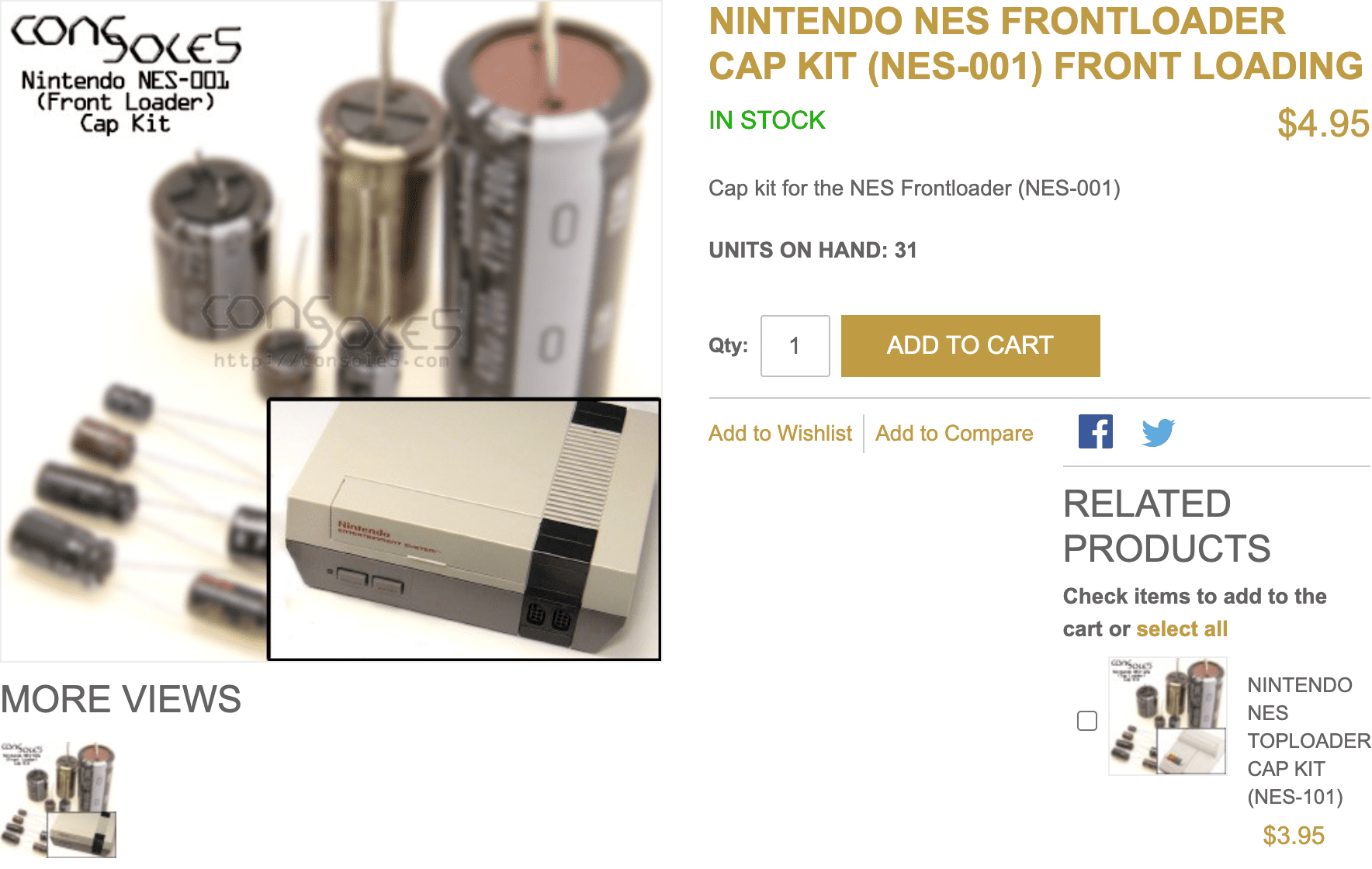
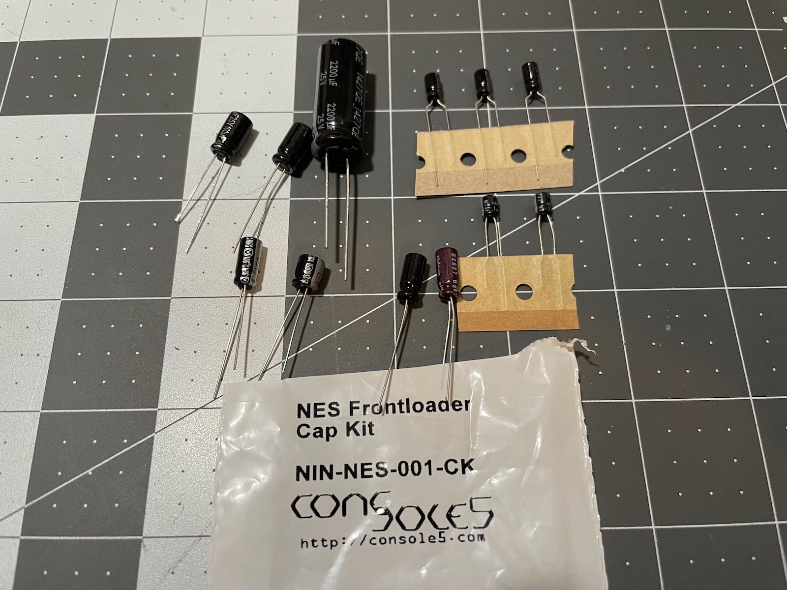
I also decided to order a new front-loader NES capacitor kit from Console5. Normally, I am happy to spec out my own caps, but $5 with a bit for shipping is probably cheaper (and a lot easier) than doing it myself.
Cleaning
With a new 72-pin connector and capacitor kit on the way, I decided to focus on the aesthetics of the console. The dirt and grime on it was pretty intense, but stuff in this condition makes for a great restoration. Even after quite a bit of scrubbing with a toothbrush and Dawn dishwasher detergent, it still looked like this… not great!
The inside was pretty nasty too. Here’s what it looked like before I started scrubbing - once again, there’s evidence that someone has been in here before.
After a ton of scrubbing, I got it to this point. Okay, but still not perfect.
Next, I attacked it with baking soda on a wet paper towel. You have to be careful as this removes a bit of the texture, but I think the results are always worth it! It’s especially powerful for black marks and scuffs.
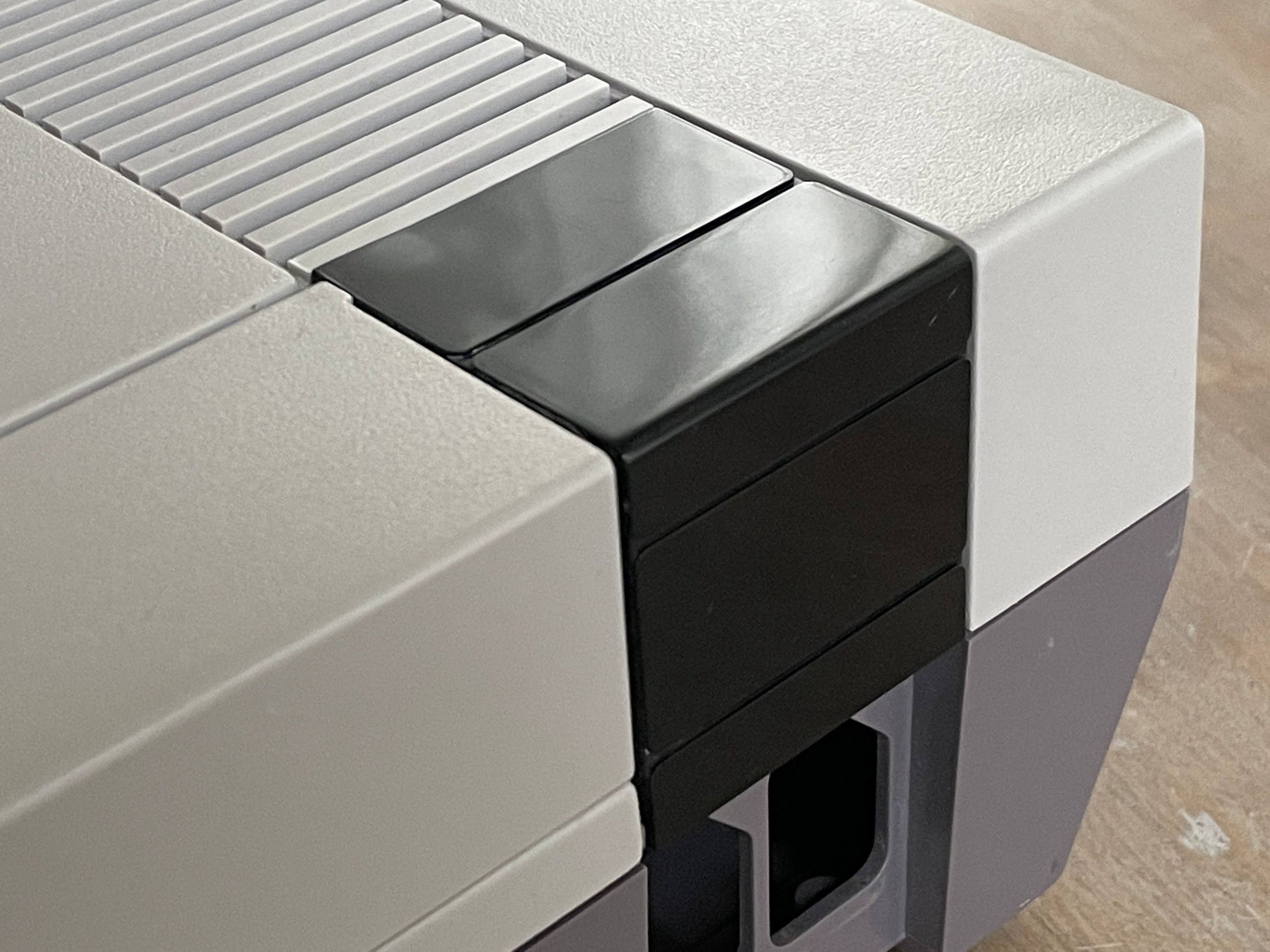
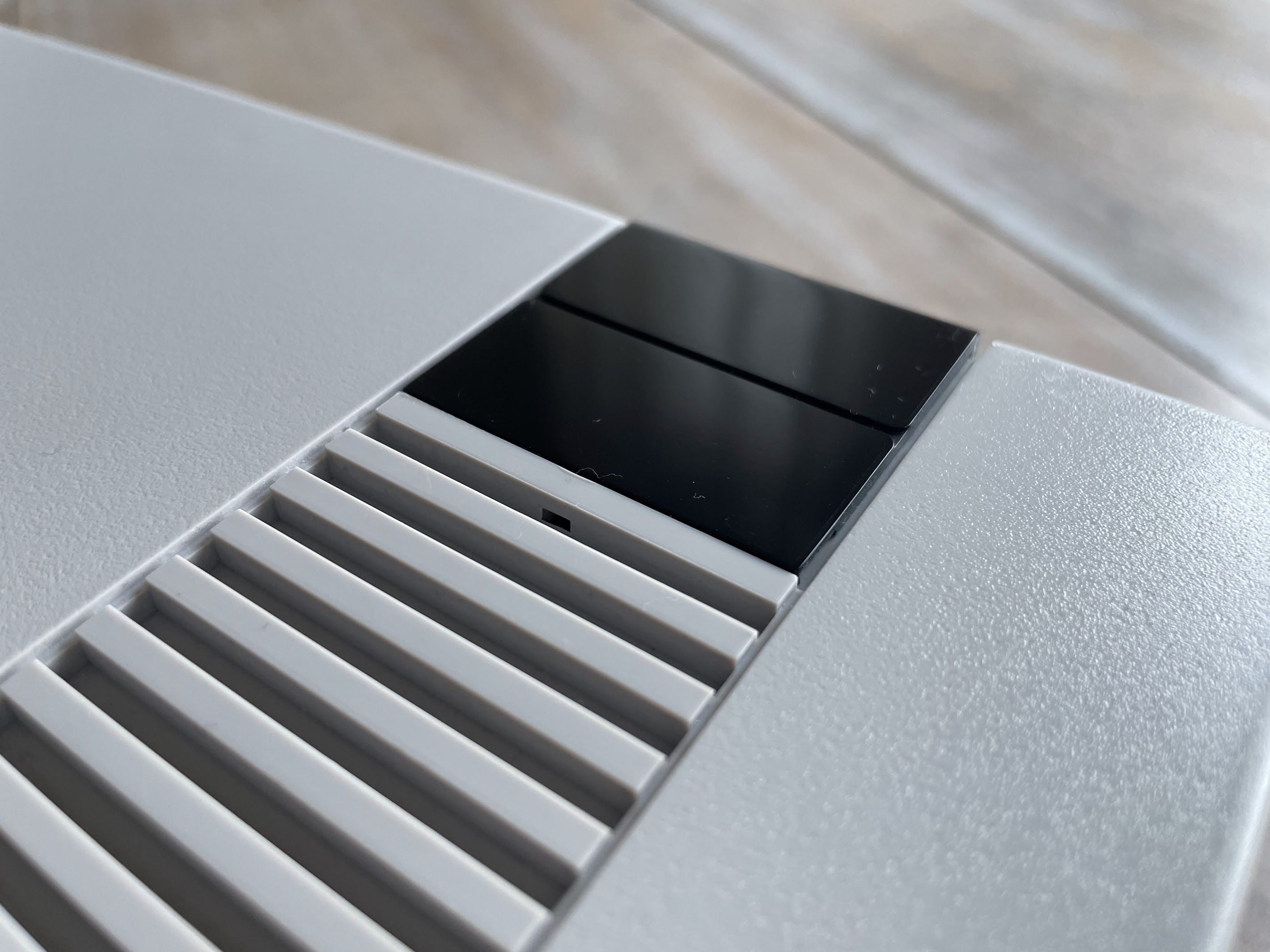
Black Plastic Restoration
With everything all cleaned up and ready for retrobrite, I decided to look into one more thing: the black plastic parts. Unfortunately, they’re pretty scratched up.
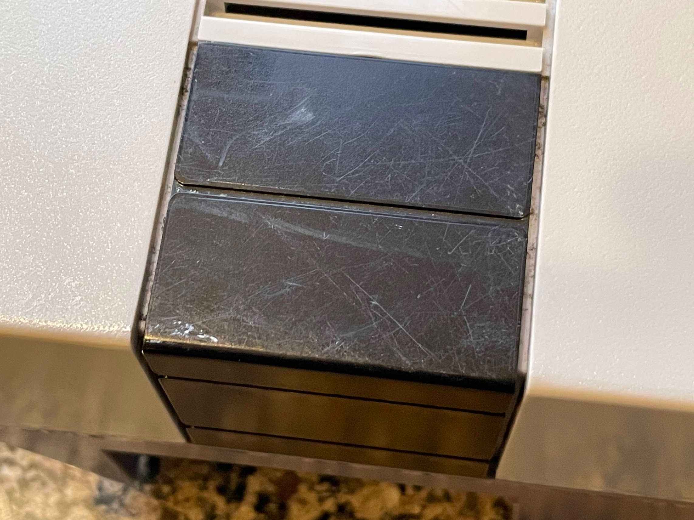
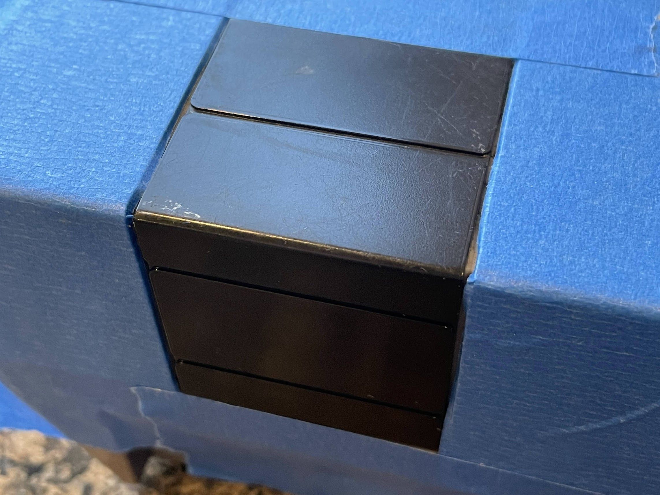
In the past, I’ve restored glossy plastic parts on consoles with wet-sanding and polishing (such as the “jewel” on the top of a GameCube). While these parts weren’t originally glossy, I decided to see what I could do. Instead of removing the parts entirely, I elected to just mask everything off.
Next, I wet-sanded them with 1000-grit, then 1500-grit, then 2000-grit, then 2500-grit sandpaper. I would have finished with 3000-grit, but I didn’t have any on hand. By the way, if you want to try this, you can get a nice little package of sandpaper in the auto detailing section at Walmart or similar supermarkets.
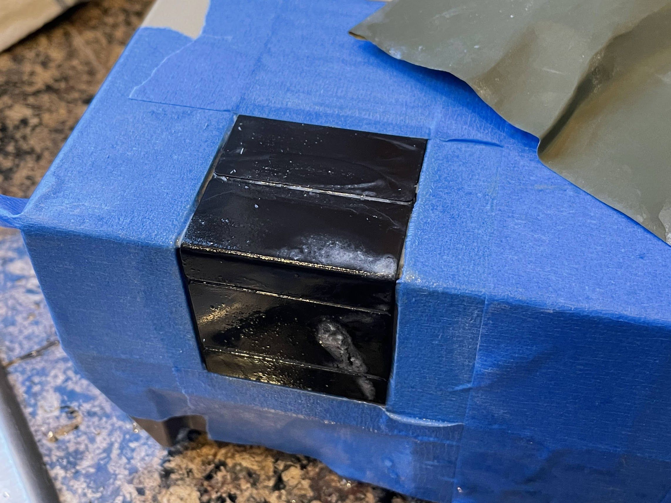
Here’s what it looked like after the 2500-grit sandpaper.
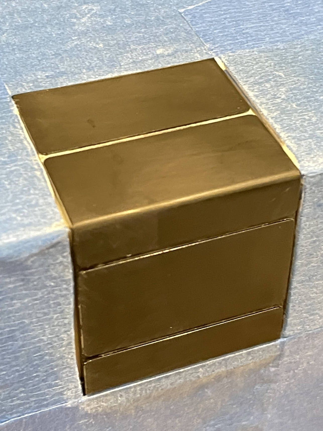
After wiping it clean, I polished it with Meguiar’s Ultimate Compound. I don’t think this is a real automotive compound (it’s probably closer to a cleaning wax), but it does the job!

I’ll hold off on revealing the results for a little bit. For now, it’s time for some retrobrite!
Retrobrite
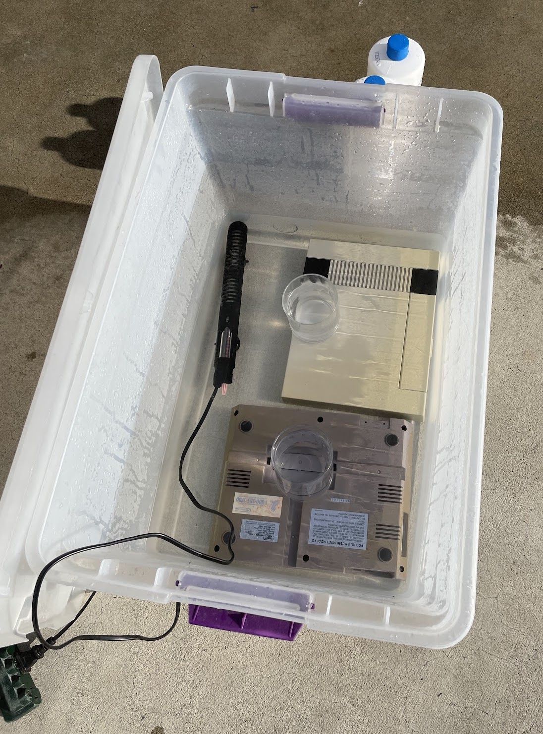
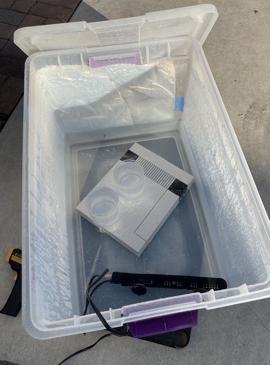
Normally, I try to do retrobrite in the summer, because heat is an important component of full-submersion retrobrite. Things typically start to move at about 38°C (100°F), but are the most effective at higher temperatures, like 40.5°C (105°F) and above. Since the ambient outdoor temperature was around 8°C (~45°F) during the day, I needed a way to increase the temperature of the liquid.
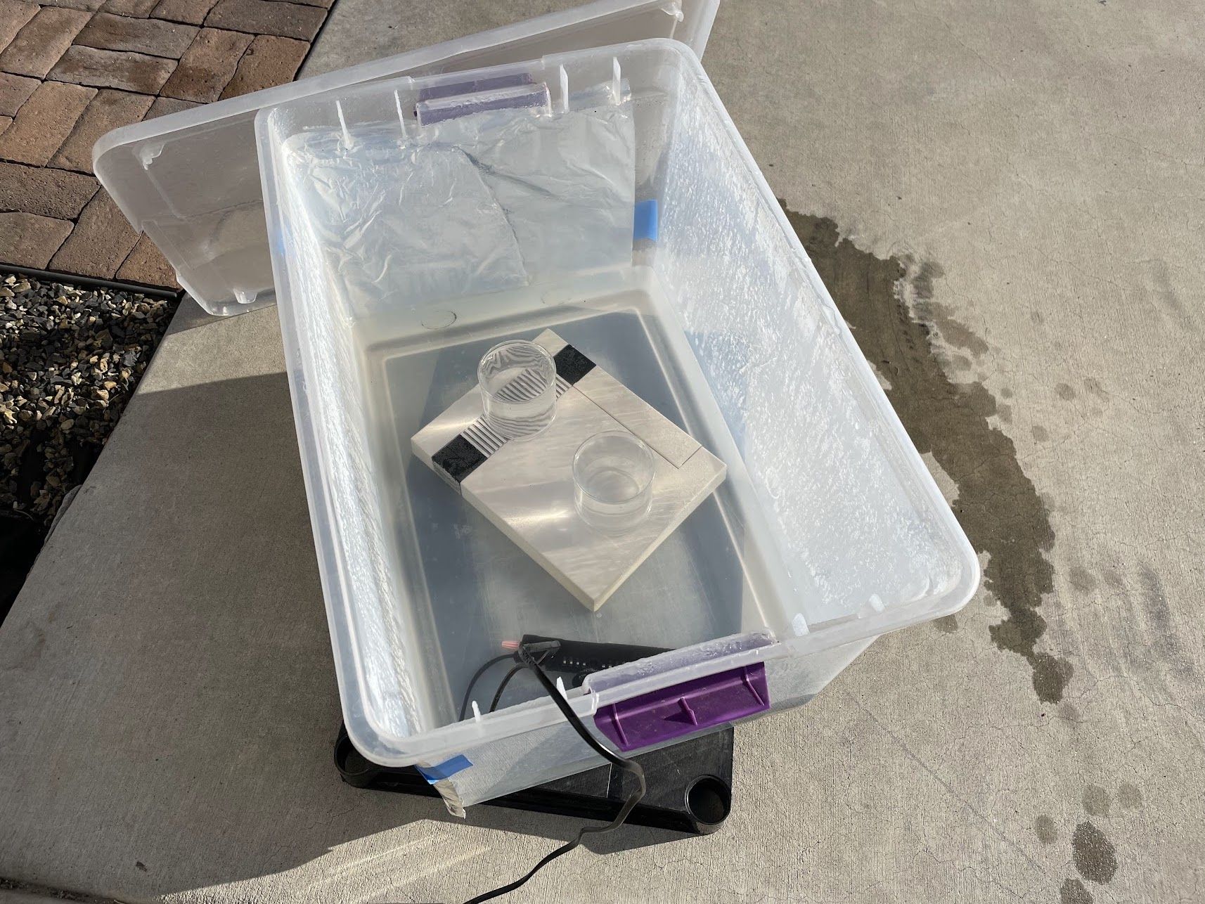
My solution is two-fold: I use some hot water from the kettle to get things started, and then I use a $10 fishtank heater to maintain the heat. If I set the plastic tub in an insulator of some kind, it can keep it at 38°C (100°F) continuously, but it can’t move it above that. To keep the parts from floating (which is super important to keep the parts from bleaching), I use a couple of glasses filled with water. They work great!
At this point, all there was to do was wait, and go rotate the bin every now and then. My neighbors must think I am really, really strange.
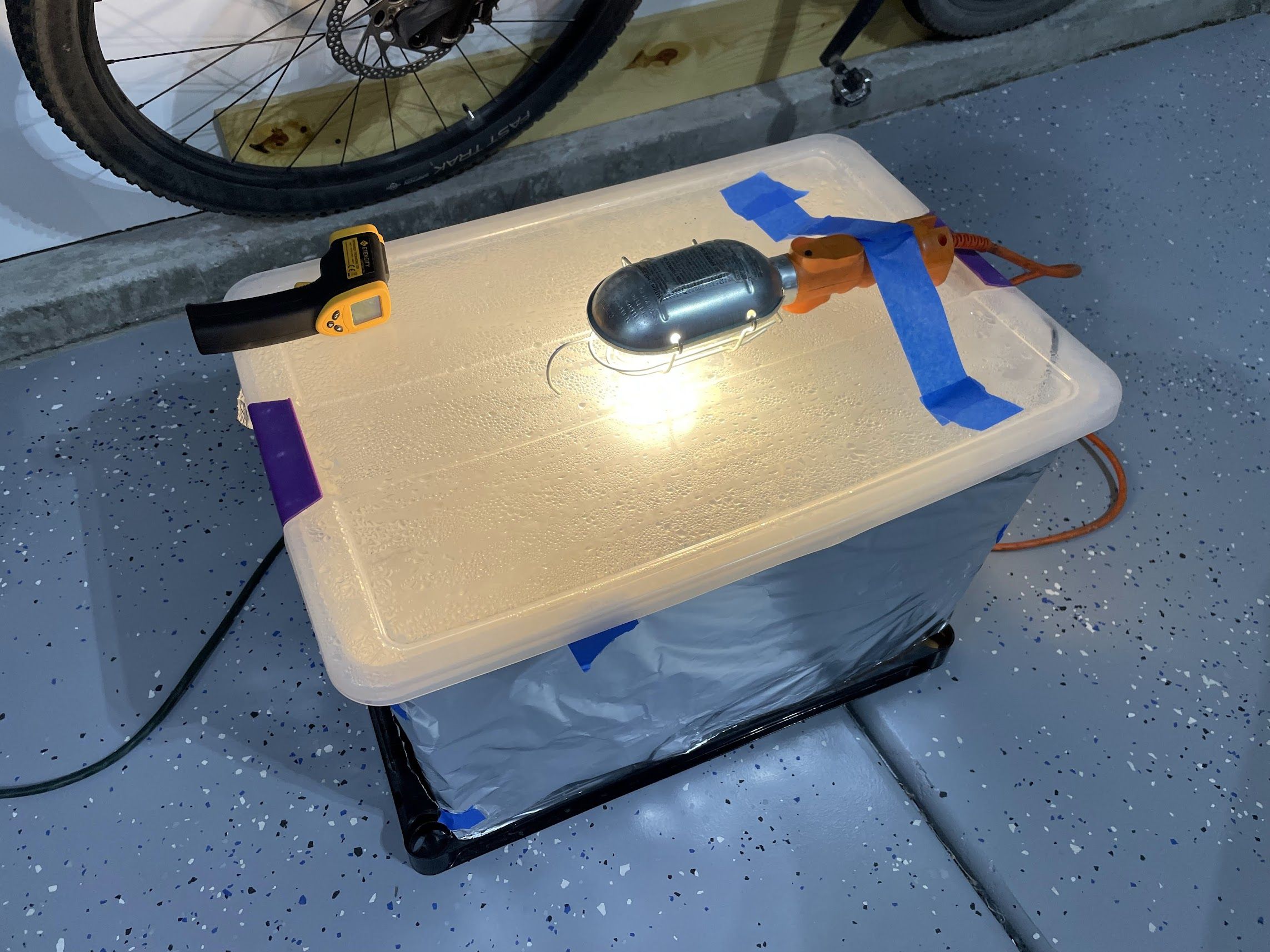
After a full day in the sun, the parts were not close to being done. I moved the setup into the garage, wrapped the outside of the bin in some aluminum foil, and placed a UV “Lizard Lamp” from PetCo on the top. I also placed a plastic shelf below the bin to act as an insulator, as the concrete was zapping a lot of the heat from the bin.
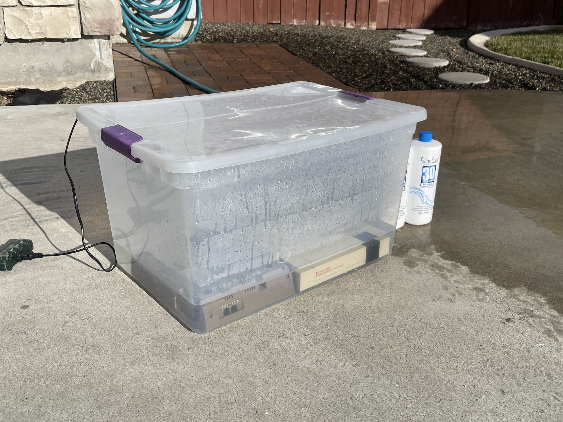
The next morning, the bottom looked great, but the top wasn’t quite there. Back into the sun - this time with the plastic insulator to help it reach full temperature.
By mid-afternoon, as the sun was closer to finishing it’s low winter-time arc through the sky, I checked on it again. It looks done! Note the bubbles everywhere - that’s a good sign that things are warm enough to be working.
Retrobrite Results
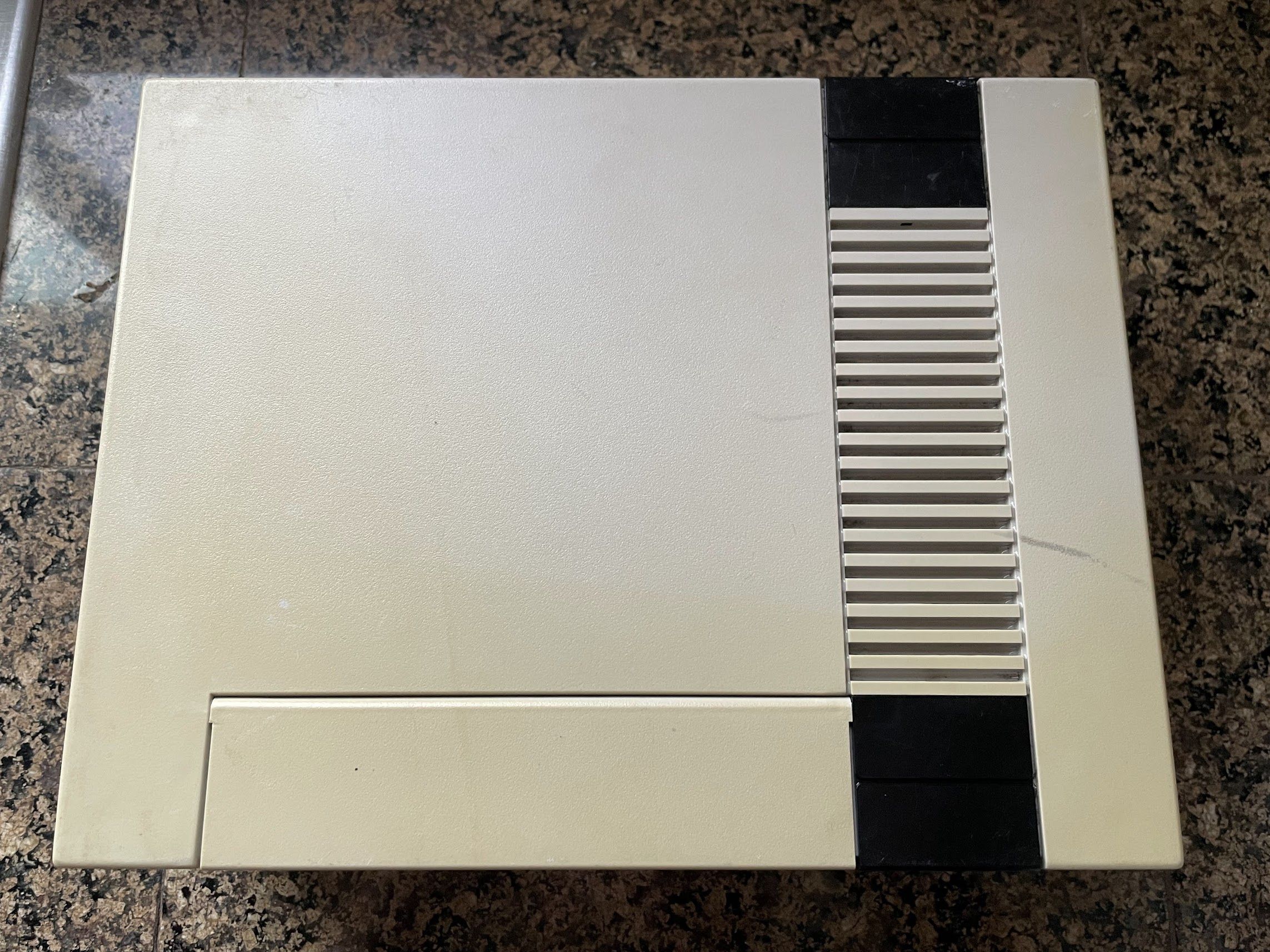
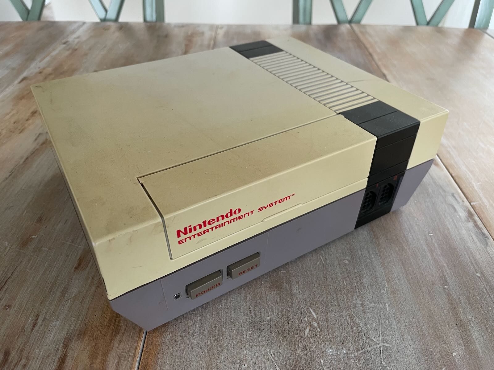
Let’s take a look at the results of the cleaning, scrubbing with baking soda, wet-sanding and polishing, and retrobrite. Here’s where we started:
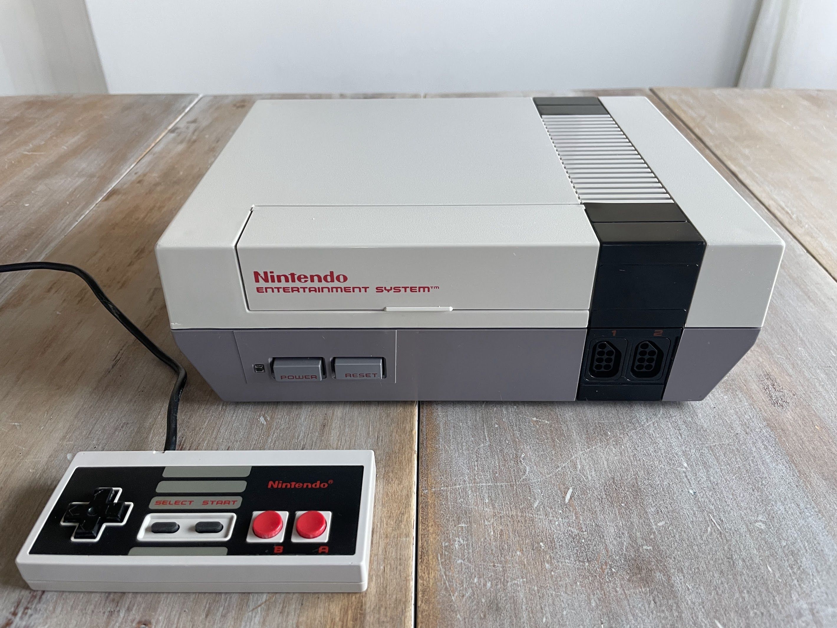
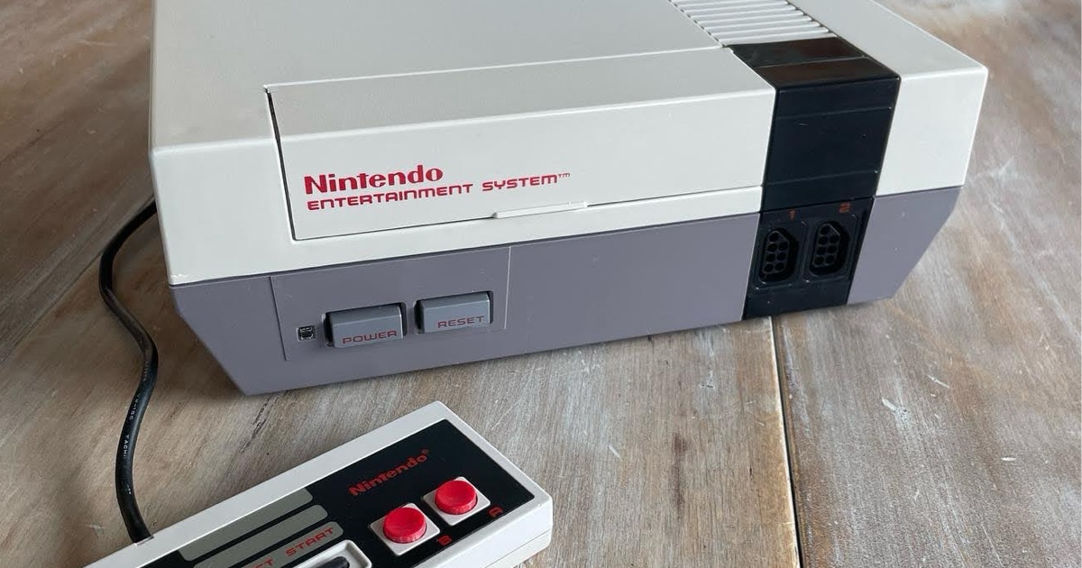
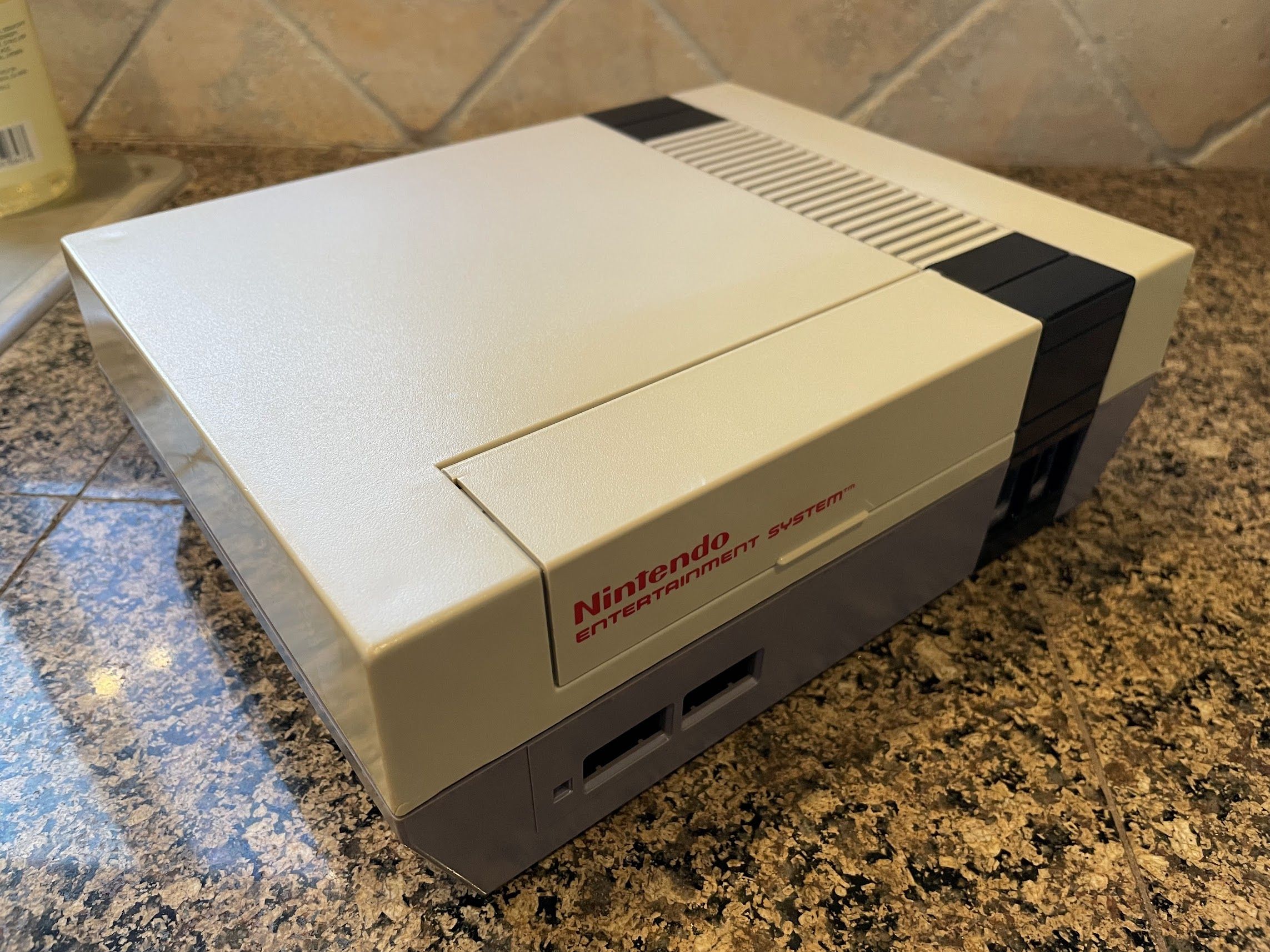
And here’s where we are now:
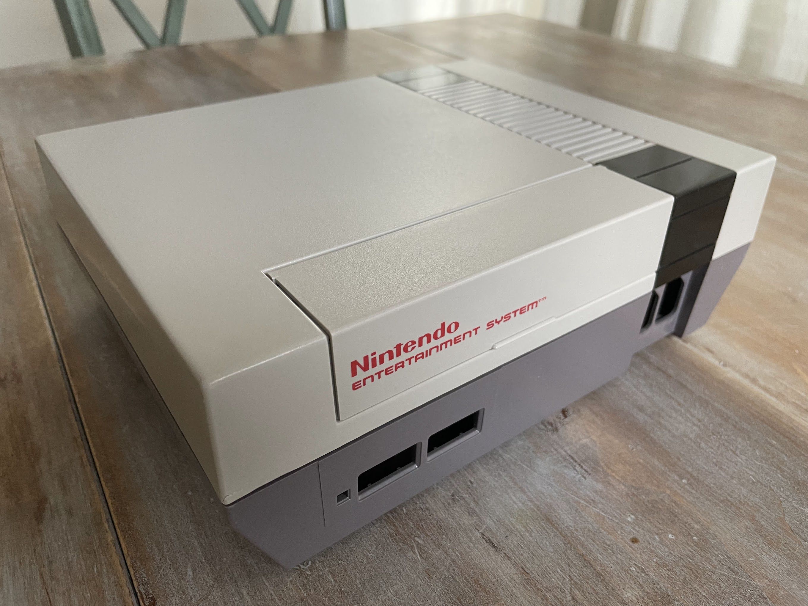
The color on the outside compares very well to the color on the inside.
Curiously, one side of the bottom is a bit “cloudy”. I’m not sure why - perhaps I didn’t clean it well enough. Normally, I only get this if I do cream-based retrobrite (which is why I almost always do full submersion these days). Fortunately, it’s not very noticable.
The bottom looks perfect.

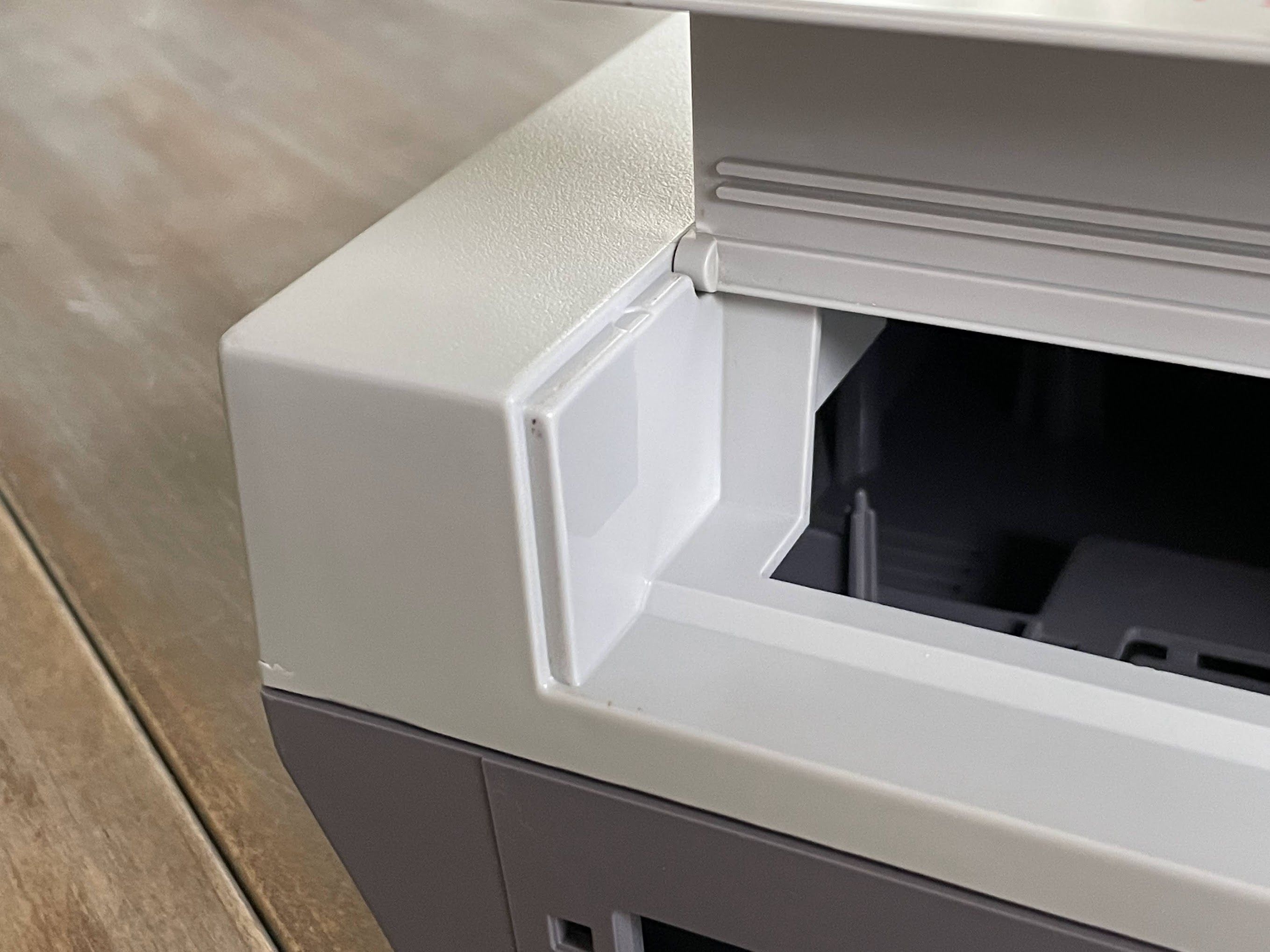
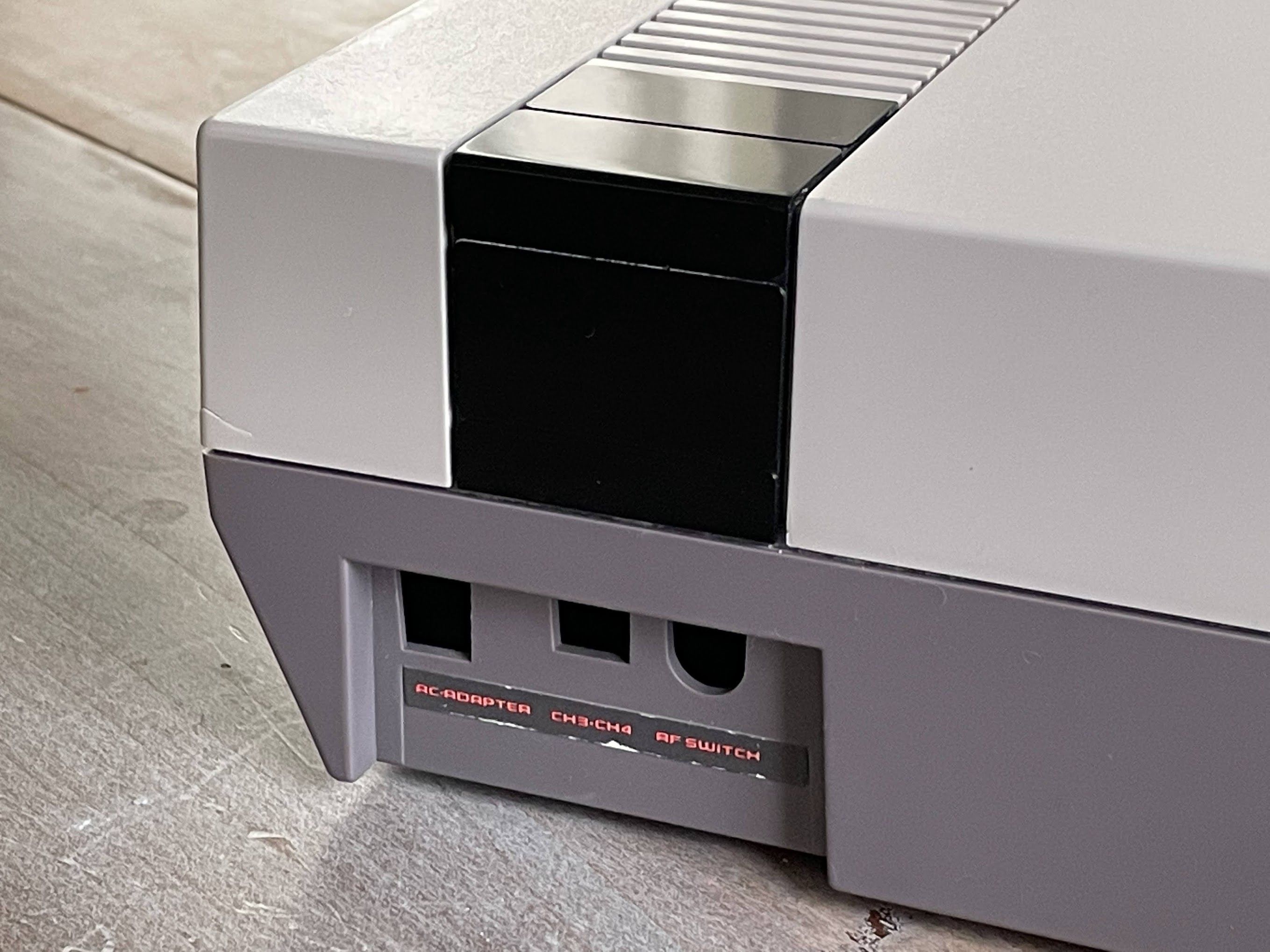
How about the black plastic? I’m very pleased with how they turned out.
Even the back looks pretty good!
Next, I’ll install the new capacitors and 72-pin connector, reassemble everything, and do a functionality test. That’s right - I haven’t actually tested this console yet. After that, I’ll need to retrobrite the Power and Reset buttons before wrapping up the project.
Capacitor Replacement
Time to install new capacitors!
I could only find 6 or 7 to replace. Perhaps the Console5 kit comes with extras for different versions of the NES, or maybe there are some non-electrolytic caps here that I’m just not finding.
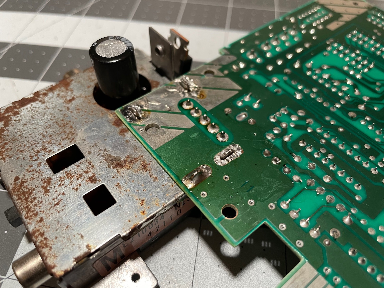
First, I need to get the RF and power enclosure desoldered.
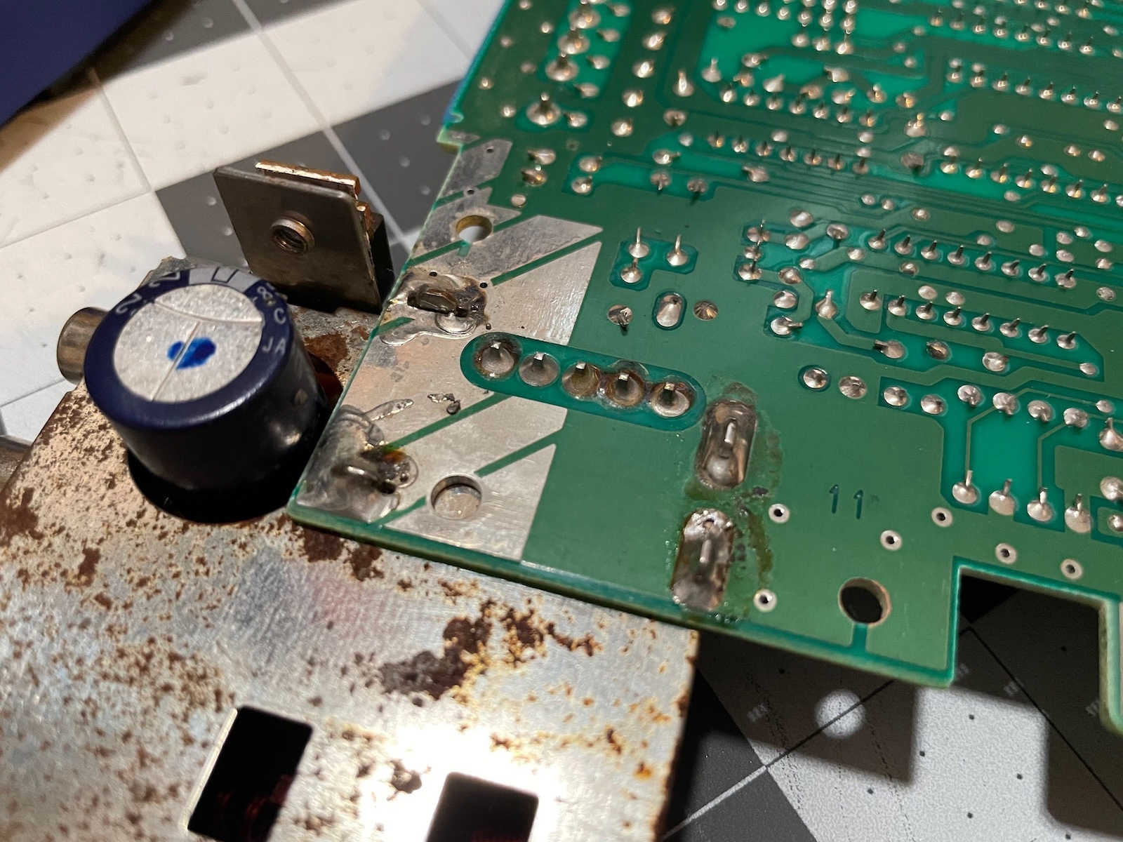
This took awhile to desolder, but I got it! I cranked the iron up to 850°F, and used the solder sucker a lot. I’m out of desoldering braid and desoldering alloy, or I probably would have used those some too. Mostly, I just tried to get the 5 pins desoldered to the point that they would freely wiggle on their own.
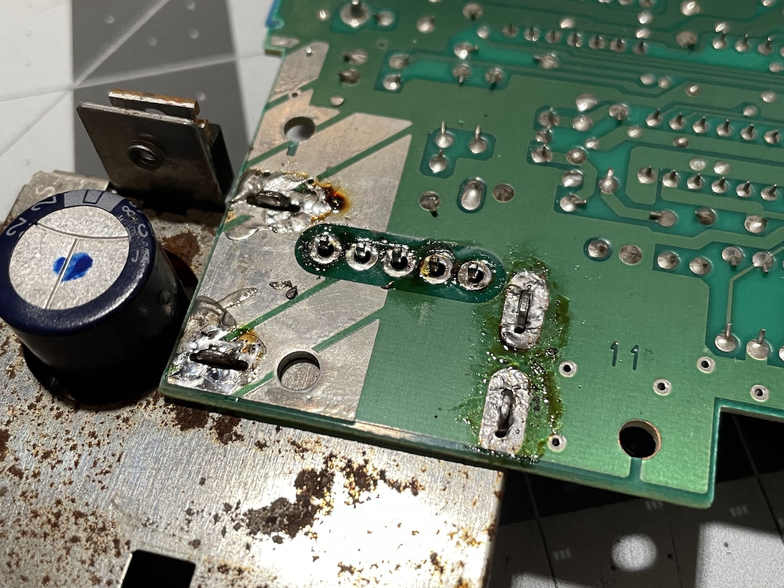
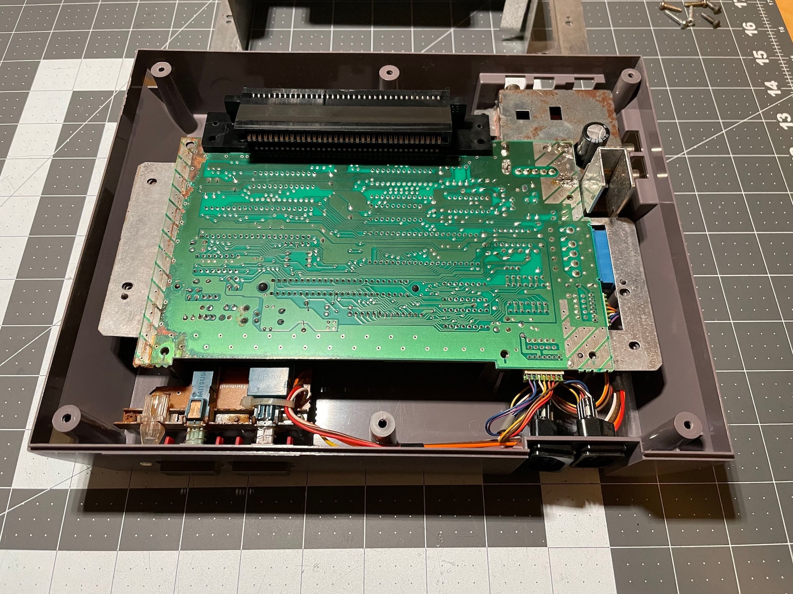
Then, after sucking as much solder away as possible, I heated up the big grounding joints one at a time, and applied upward pressure until they popped out. Time consuming, but not a big deal.
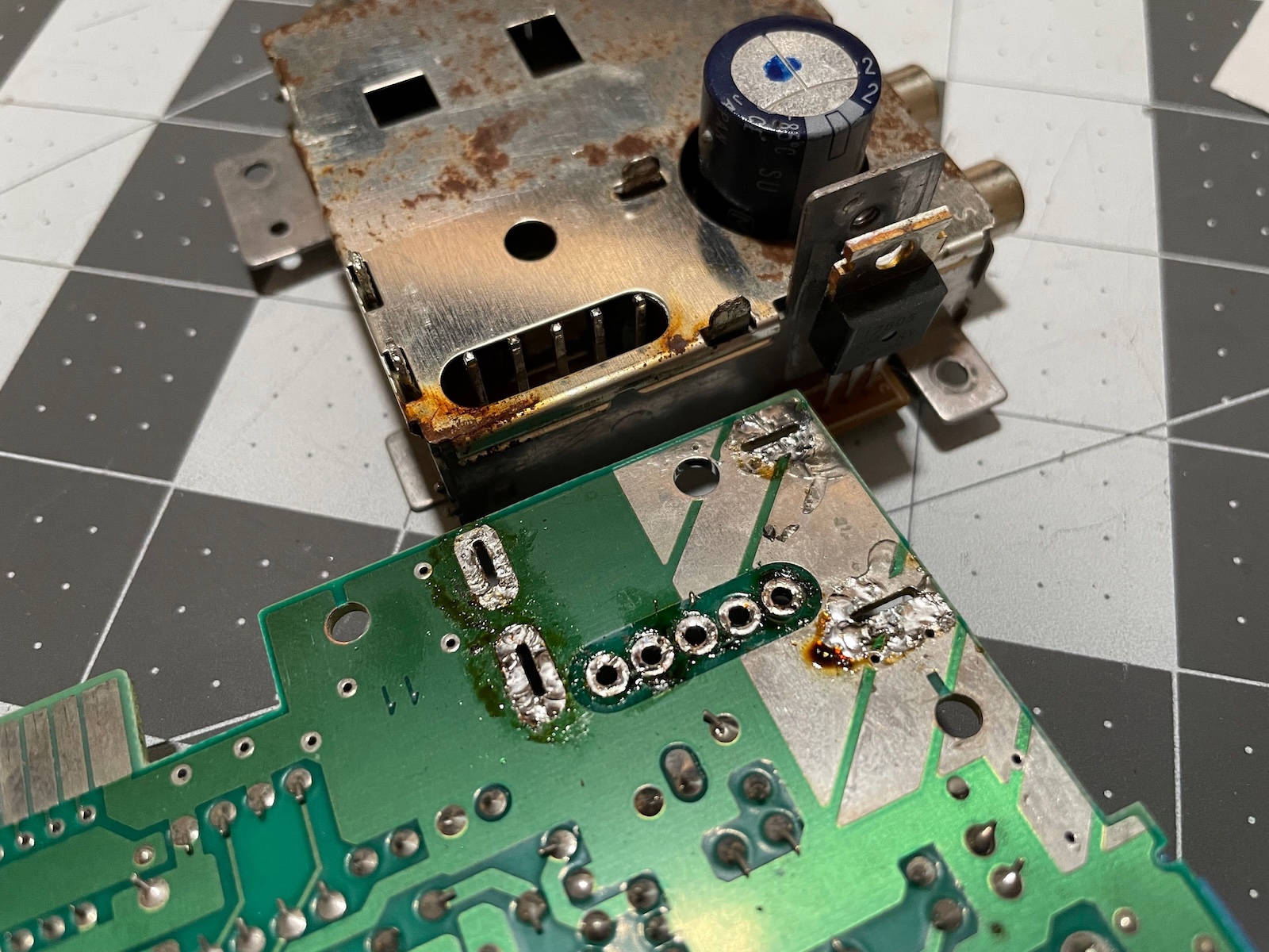
I used a small screwdriver to pop the top off the RF and power box.
We’re in! First, I desoldered the big capacitor. Then, I swabbed everything out with alcohol, and replaced the three little caps one at a time. Here they are, all replaced.
I also dropped the small RF shield into some vinegar to work on the rust. The screws cleaned up SUPER well, but the shield did not. Oh well.
With the big capacitor reinstalled, and the three caps on the main board replaced, it was time to reassemble!
I soldered all 5 pins, but I only soldered in one ground connector, just in case it needs to come back apart for some reason. I’ll come solder them up later once I see everything working.
Reassemble and Test
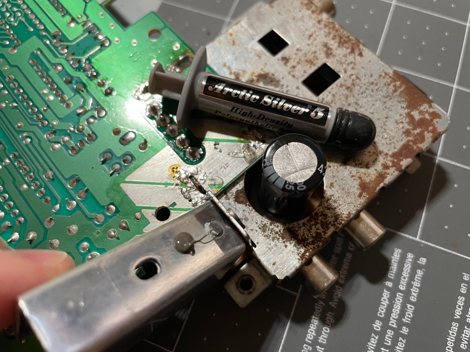
At this point, the next thing to do is partially reassemble and test. I used some fresh thermal paste on the regulator (both here, and on the regulator itself).
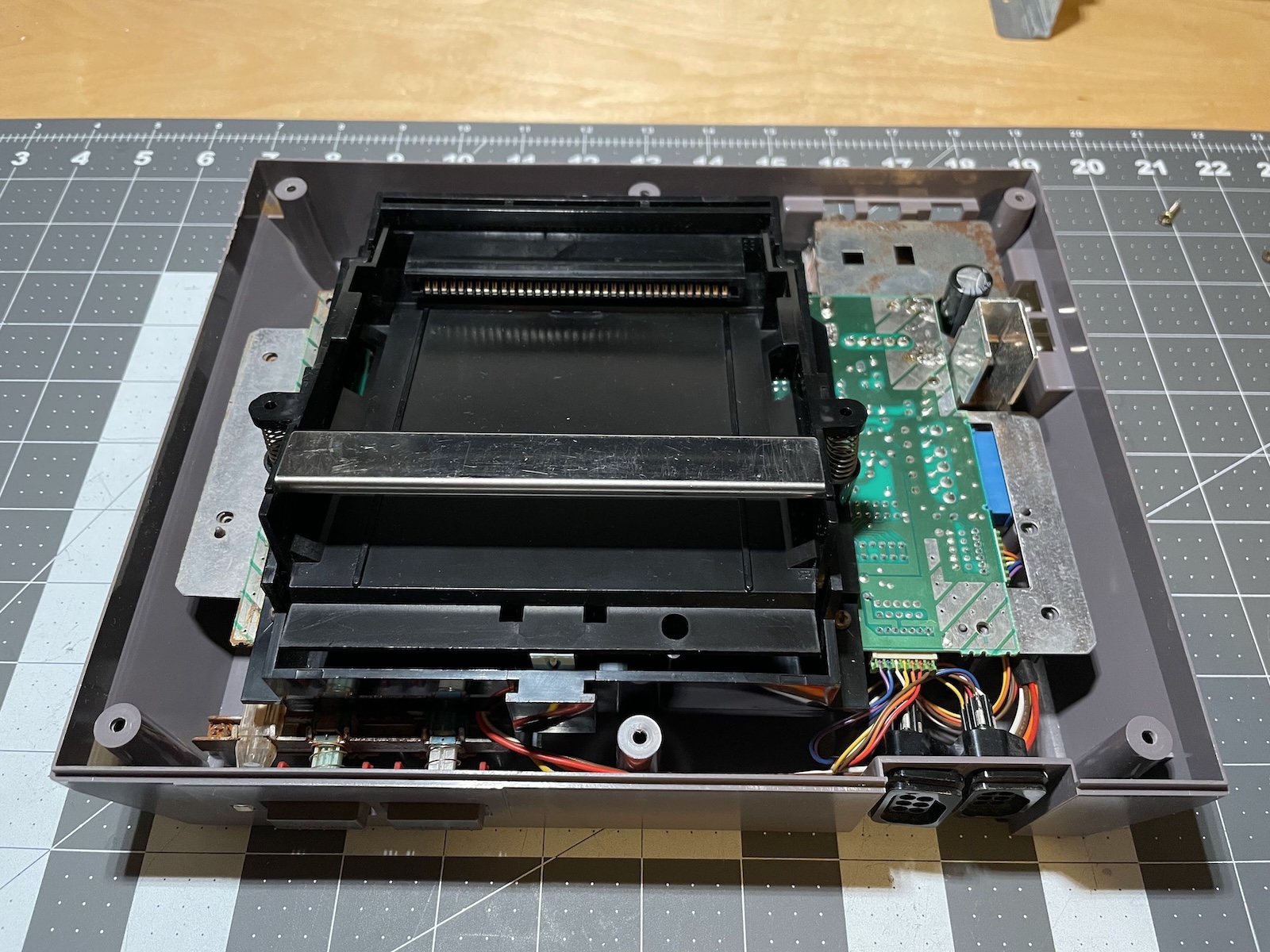
Next, I seated the RF shield on the main board, dropped everything into the NES, and plugged in the power and controller connectors.
Next, I cleaned and installed the tray. I had some trouble getting it to seat properly.
Time for the moment of truth! I swapped out my working NES for this one.
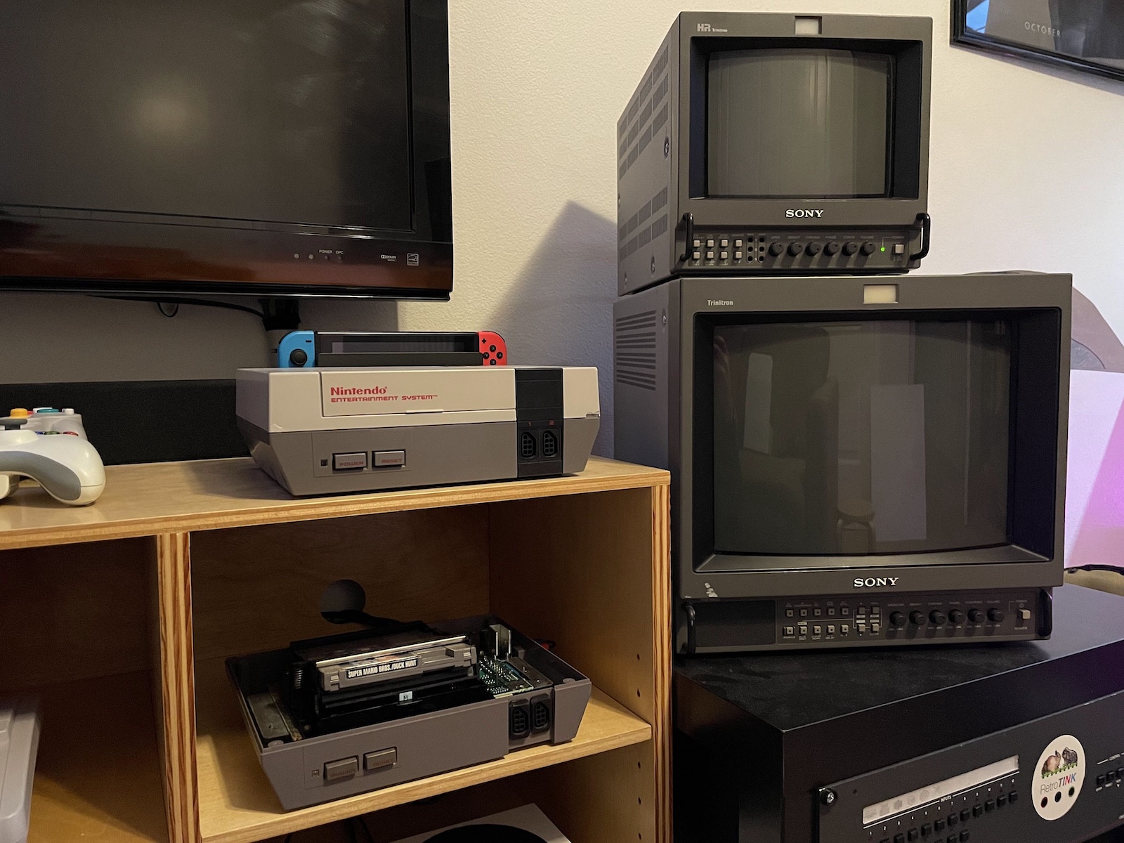
When I powered it up without a game, the screen flashed pink and blue! Interesting - my other NES does not do that, but it also has the 10NES lockout/CIC chip disabled. I installed a copy of Duck Hunt/Super Mario Bros and…
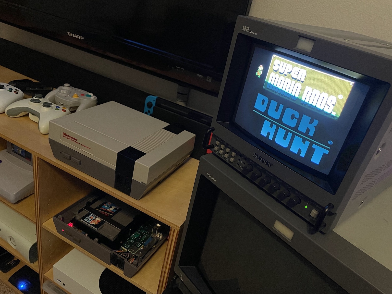
It works! Yes! One thing I will say about the 72-pin connector that I bought is that it’s pretty stiff! It takes a firm push and pull to cycle the cartridge - much more than my other NES does. I am going to leave my copy of Duck Hunt in there for a couple of days to see if that helps loosen it up.
So, what’s left?
- Clean and install the controller connectors.
- Clean and retrobrite the Power and Reset buttons. They feel pretty rough when you press them, but they do work.
- Restore the controller.
Power and Reset Buttons
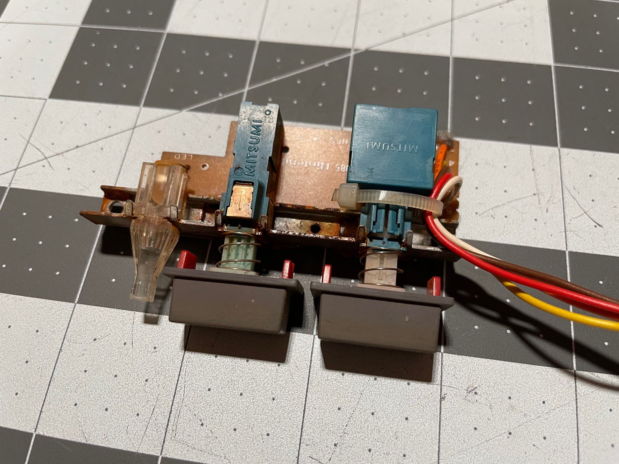
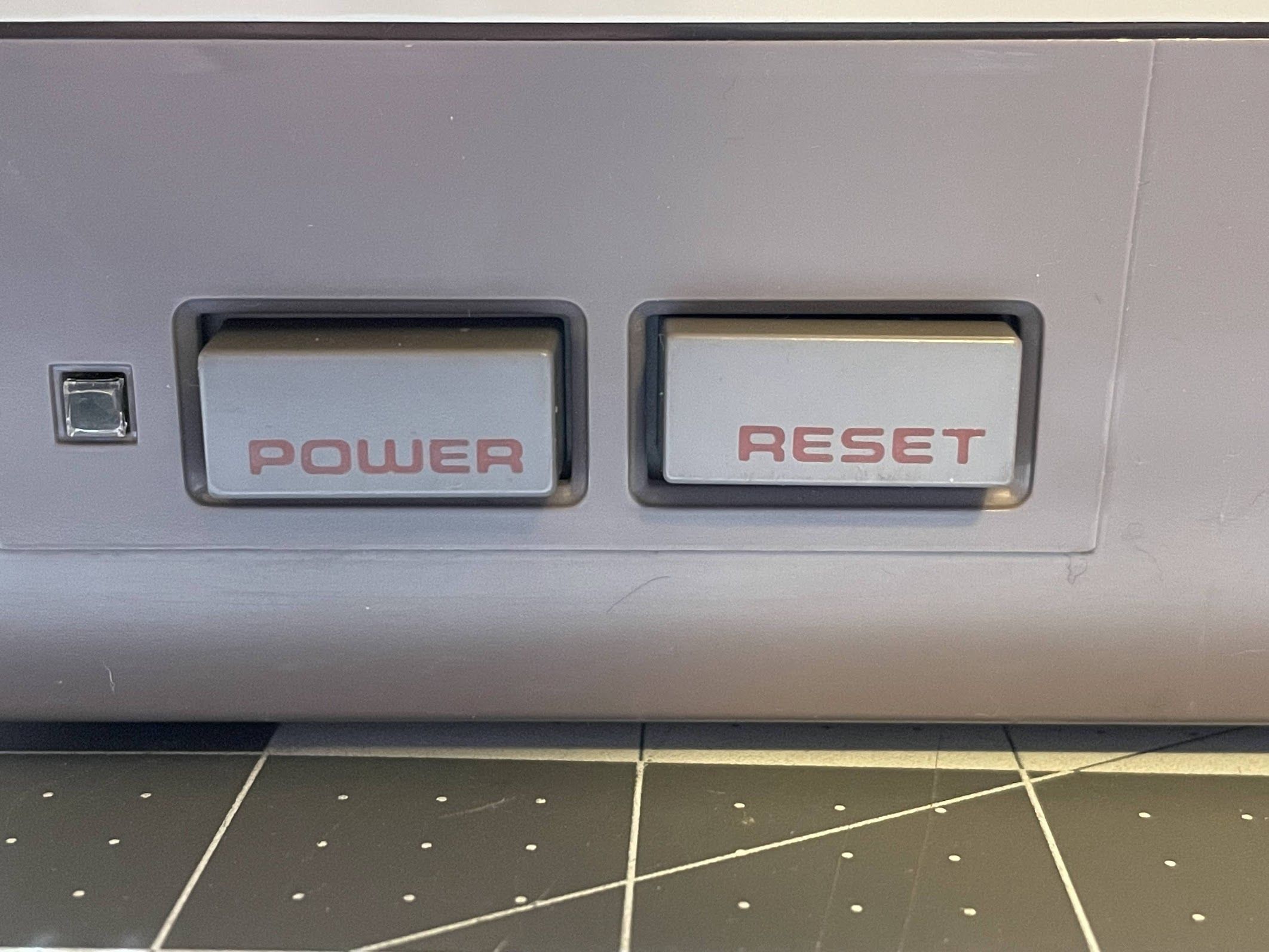
This project is getting very close to completion, but there are a couple of things left to do. One of them is sort out the very brown Power and Reset buttons. In addition to looking bad, they also feel kinda crunchy and rusty. They do work though, so that’s a good start!
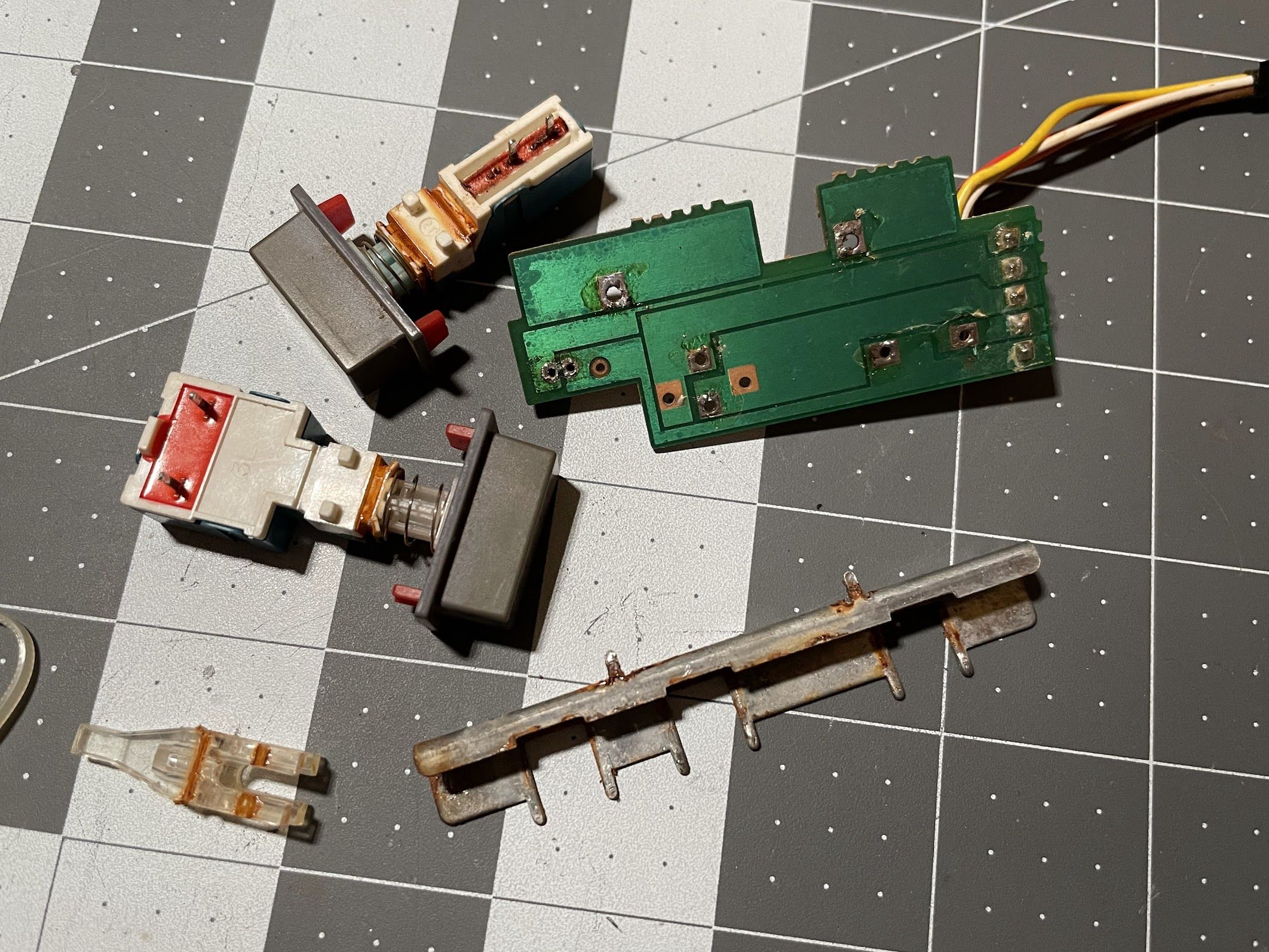
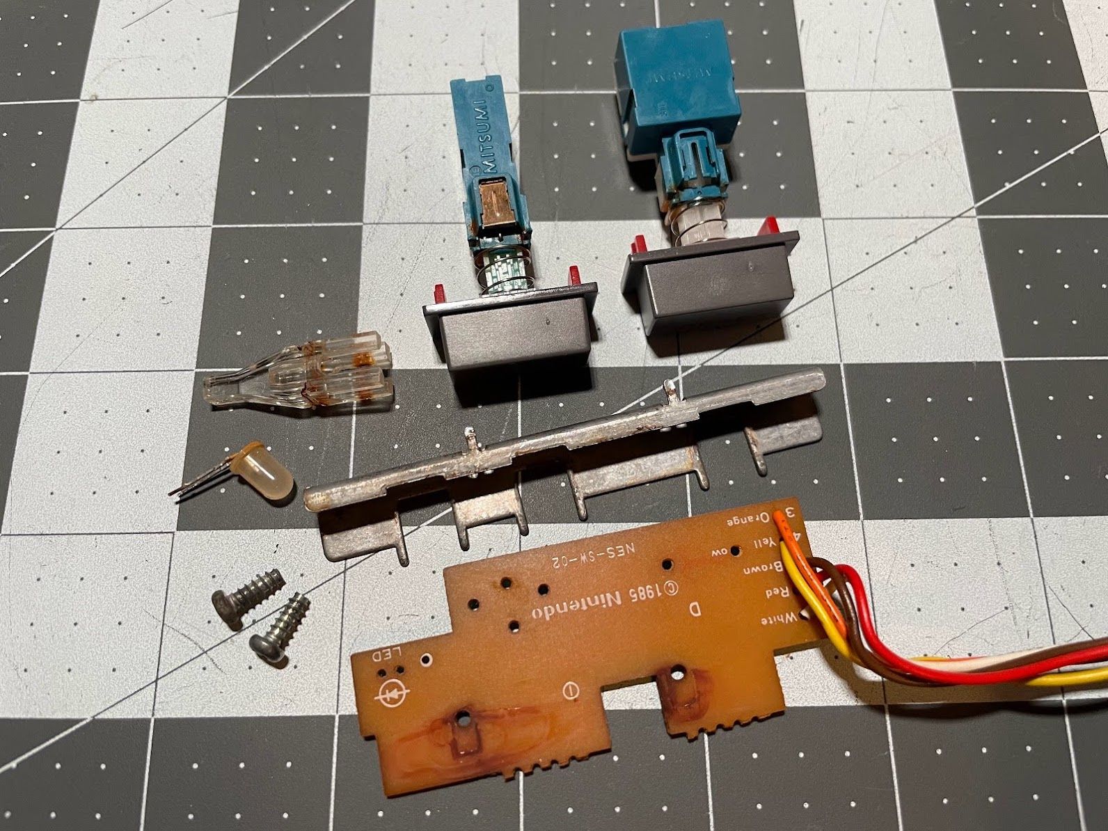
First, I desoldered the power switch, reset switch, and LED from the PCB.
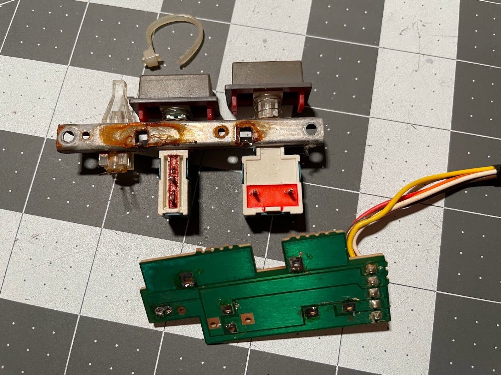
Next, I used some needlenose pliers to bend these little tabs up, so I could wiggle the switches and LED light pipe out.

With everything disassembled, I could get it all cleaned up.
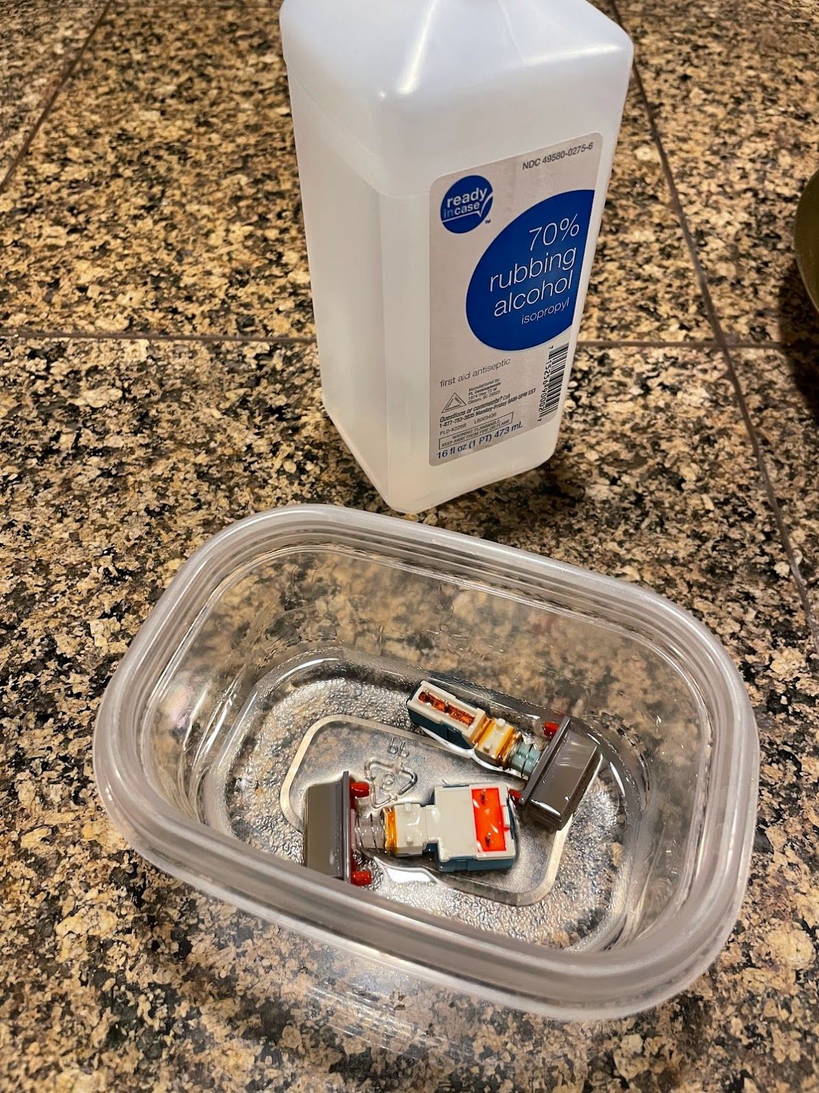
First, I used some Isopropyl Alcohol to try to flush the switches out. I submerged them, actuated them, and re-submerged them over and over. The graveling feeling didn’t quite go away, but it did get a lot better.
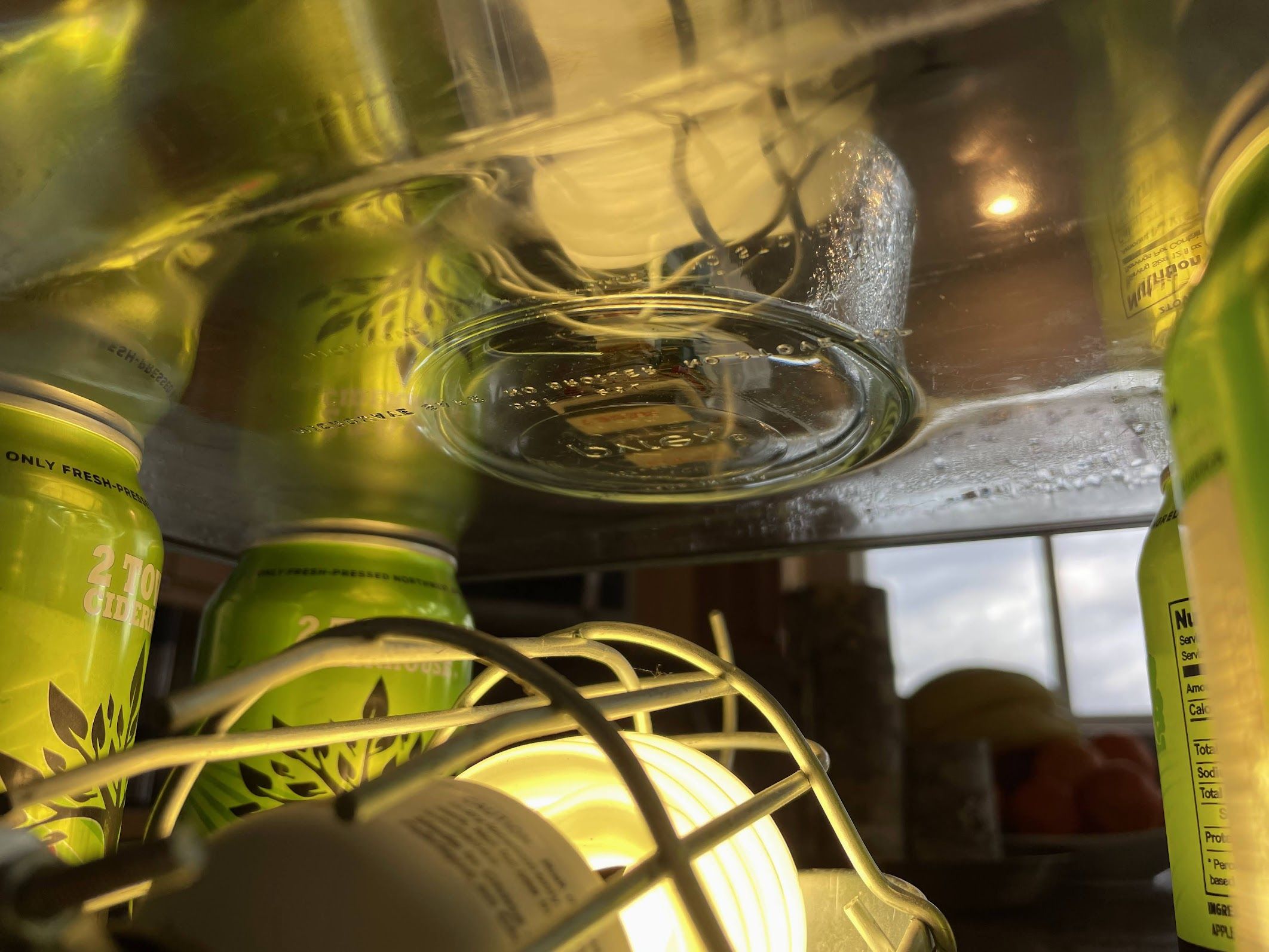
Next, I rigged up this very safe retrobrite system. I filled a small Pyrex dish with 30 or 40-proof clear developer (e.g., high-percentage Hydrogen Peroxide) just enough to submerge the plastic part of the switches. I used a bit of tape to keep them standing up. Then, I filled the larger Pyrex dish with hot water, suspended it on four 2 Towns cider cans, and placed my UV “Lizard Lamp” below everything. I taped the lamp cord down to make sure it couldn’t move on accident, and upset the water. There are some obvious safety issues here… so I don’t recommend trying this at home.
Eventually, I did drop my little fish tank heater in there, which brought it up to a nice 38°C/100°F. After a day of that, the switches looked nice and grey.
Off-camera, I also soaked the metal bracket (and screws) in vinegar to take care of the rust.
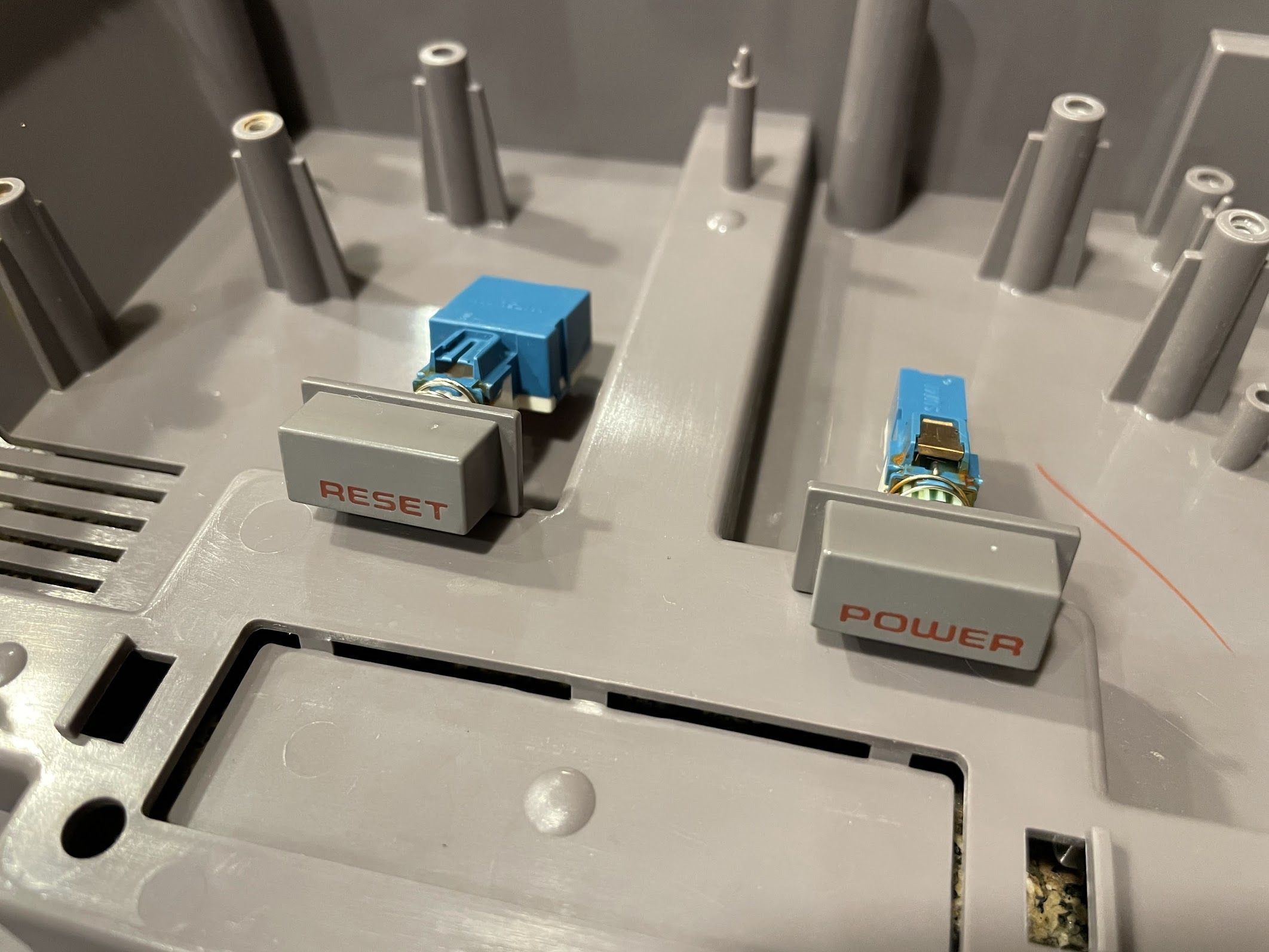
I soldered the PCB back on to the bracket, reinstalled the switches and LED, and bent the little tabs in slightly.
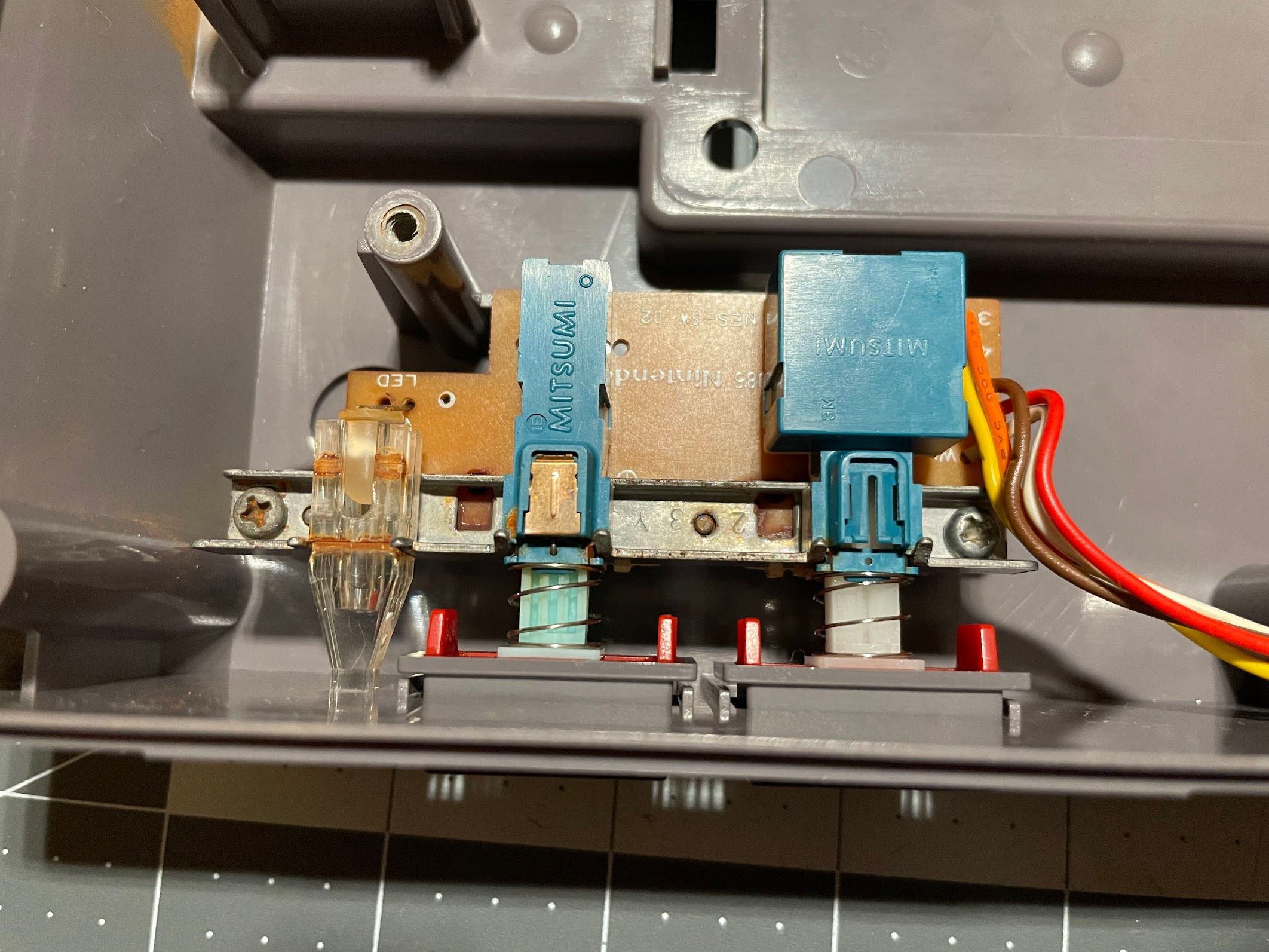
For some reason, the Reset switch is slightly crooked, but you can only tell when you get up close and personal like this. No casual observer would ever notice this though, so I am not going to worry about it.
Controller
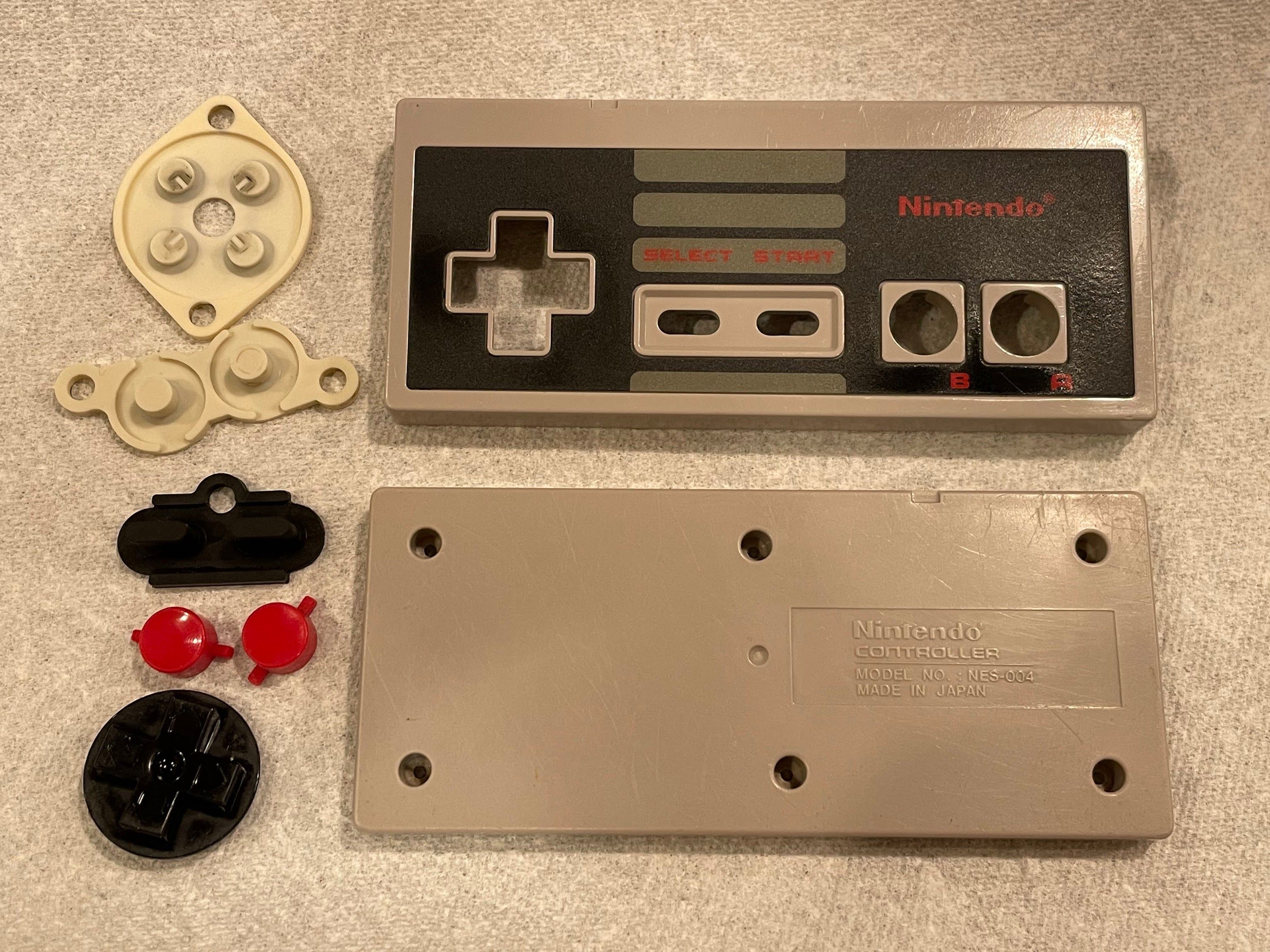
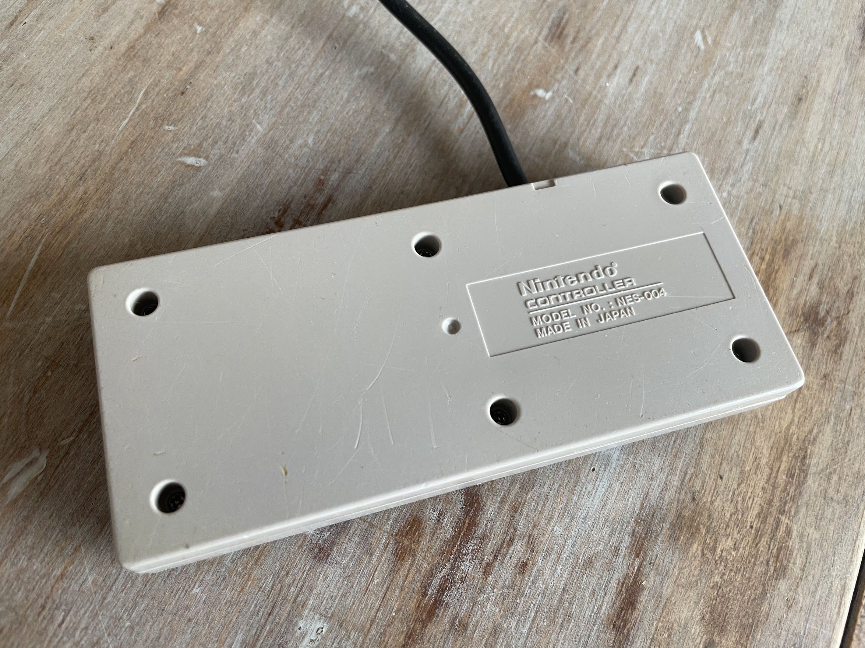
There’s just one more thing left to finish up this restoration: the controller! Let’s get after it! First, let’s attempt to survey the damage with this blurry photo.
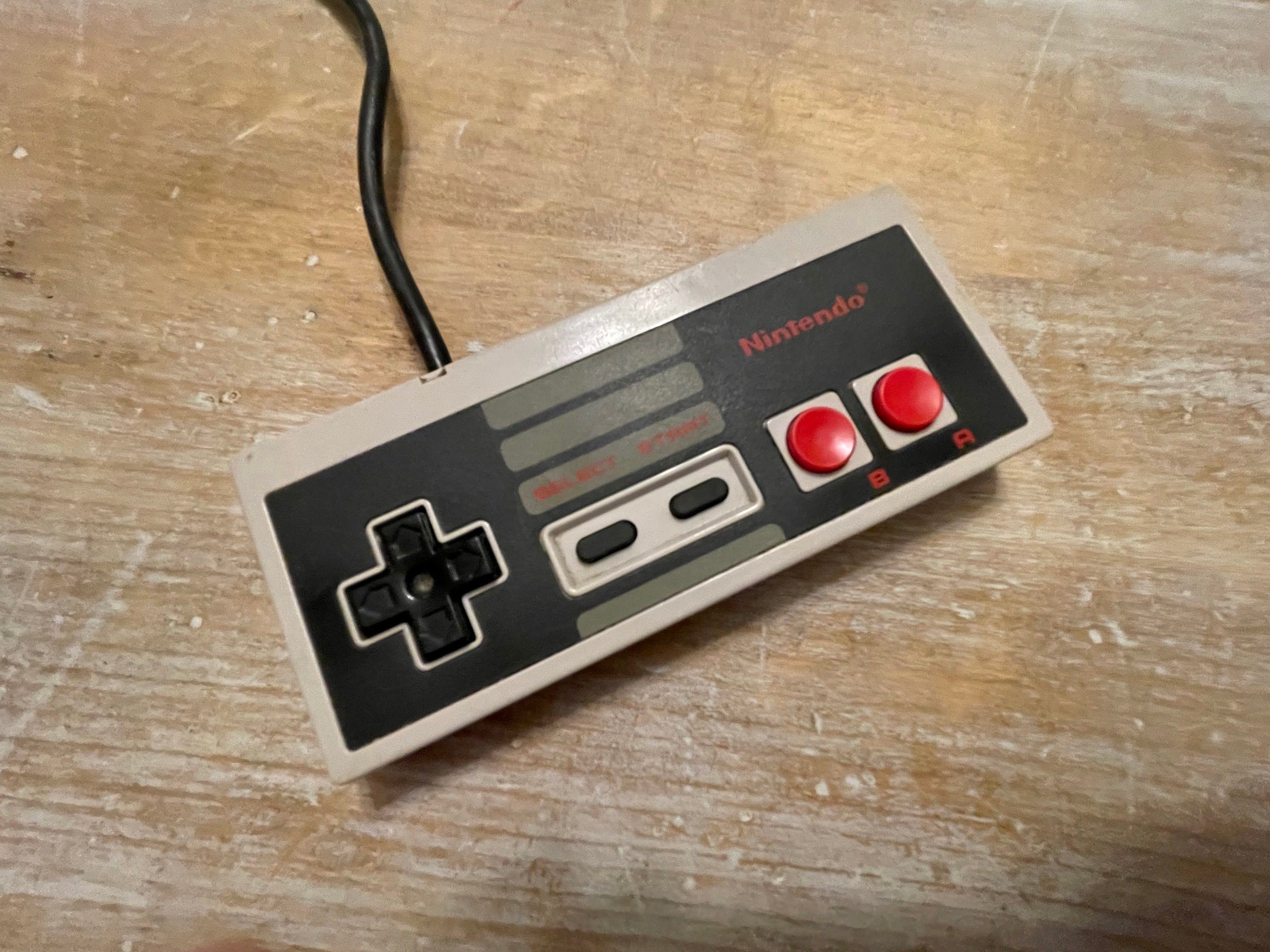
Hmmm, okay. Not bad let’s look at the ba- OH MY GOSH.
Yikes. This is going to take some work to clean up. Did someone play with these on a concrete floor or something?
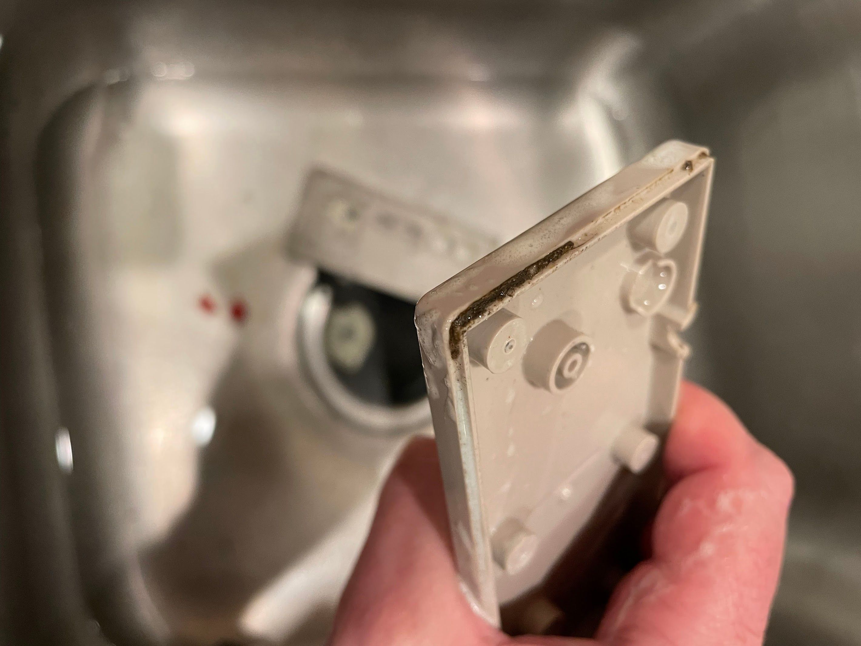
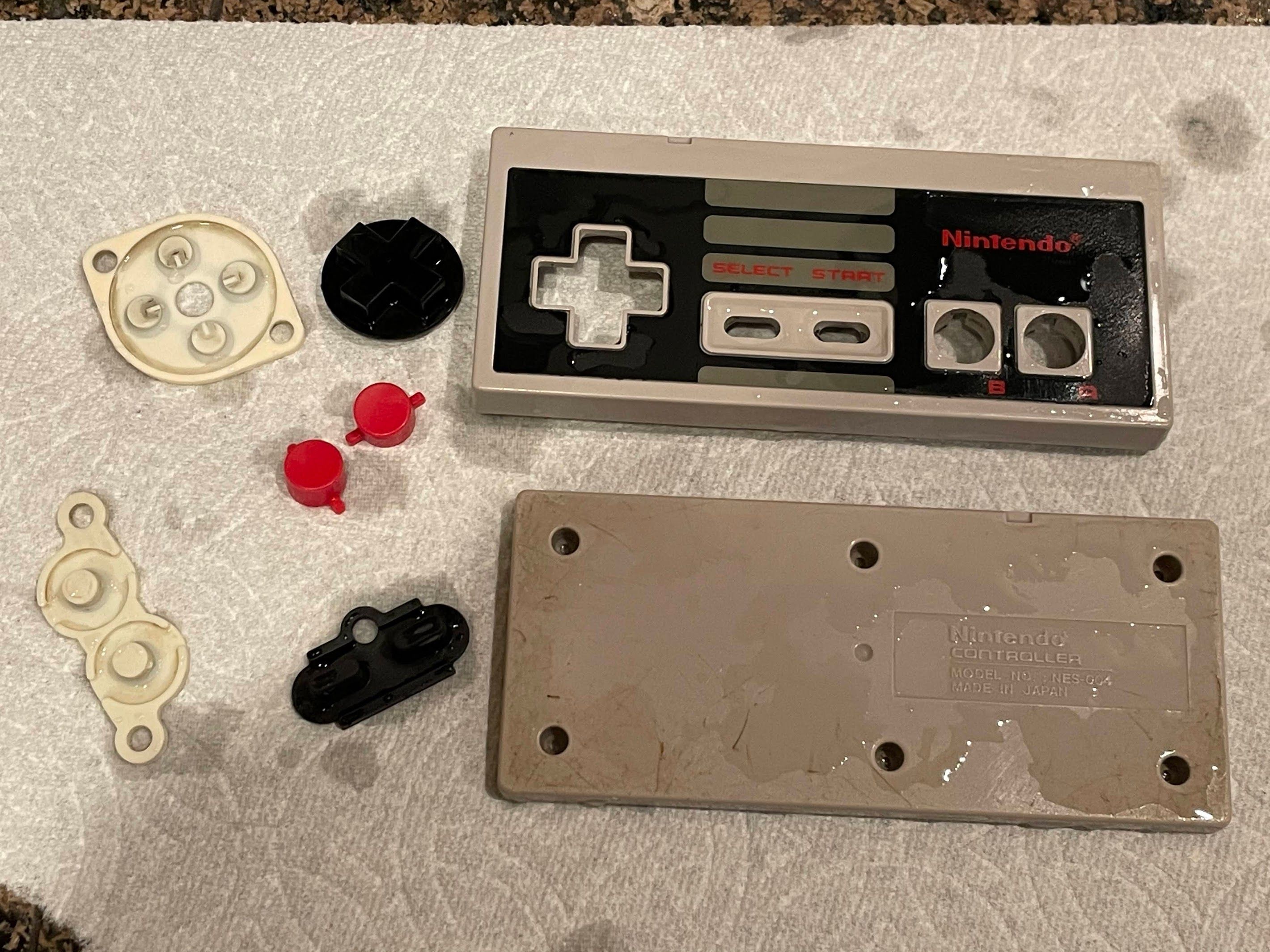
Into the sink it all goes for scrub with warm water and dishwasher detergent, all with a toothbrush! It was pretty gross - this is why I always take everything clear apart for cleaning - especially game controllers!
Here it is after cleaning with a toothbrush and soap. Still not great, but better!
Next, I used alcohol and q-tips to try to clean up the rubber domes some more. After that, I attacked the back of the controller with a wet paper towels and baking soda. You know the drill - this works as a mild abrasive, simultaneously digging dirt and grime out of the scratches, and removing a bit of material around the scratches to smooth them out. At this point, I wasn’t worried about maintaining any of the texture, as it was pretty wrecked!
And that’s it!
Results
Now, we’ll reassemble and take a look at the results. Just to remember where we started, here’s before:
And here’s after!
I’m very happy with how the black plastic parts turned out after wet-sanding and polishing!
And let’s not forget about the back of the controller.
And with that, our restoration thread draws to a close! Thank you very much for following along - I hope you enjoyed it!